
Method of forming oxide film and oxide deposition apparatus

a technology of oxide film and oxide deposition apparatus, which is applied in the direction of coating, chemical vapor deposition coating, metallic material coating process, etc., can solve the problems of empty spaces such as voids, and the conventional oxide film manufacturing method cannot meet such requirements, and achieve excellent step coverage and uniform thickness

Active Publication Date: 2007-10-11
JUSUNG ENG
View PDF8 Cites 29 Cited by
  • Summary
  • Abstract
  • Description
  • Claims
  • Application Information

AI Technical Summary

Benefits of technology

[0007]The present invention is to provide a method of forming an oxide film with uniform thickness and excellent step coverage through an atomic layer deposition (ALD) process using any one of SiH4, Si2H6, Si3H8, tetraethylorthosilicate (TEOS), dichlorosilane (DCS), hexachlorosilane (HCD) and trisilylamine (TSA) as a source gas, and an oxide deposition apparatus.

Problems solved by technology

However, conventional oxide film manufacturing methods could not satisfy such requirements.
However, empty spaces such as voids are generated between patterns, and an oxide film is not formed on sidewall surfaces of the patterns since uniform thickness or high step coverage of the oxide film can not be satisfied.

Method used


Image

  • Method of forming oxide film and oxide deposition apparatus
  • Method of forming oxide film and oxide deposition apparatus
  • Method of forming oxide film and oxide deposition apparatus

Examples


Embodiment Construction

[0027]Hereinafter, preferred embodiments of the present invention will be described in detail with reference to the accompanying drawings. However, the present invention is not limited to the embodiments disclosed below but may be implemented into different forms. These embodiments are provided only for illustrative purposes and for full understanding of the scope of the present invention by those skilled in the art. Throughout the drawings, like reference numerals are used to designate like elements.

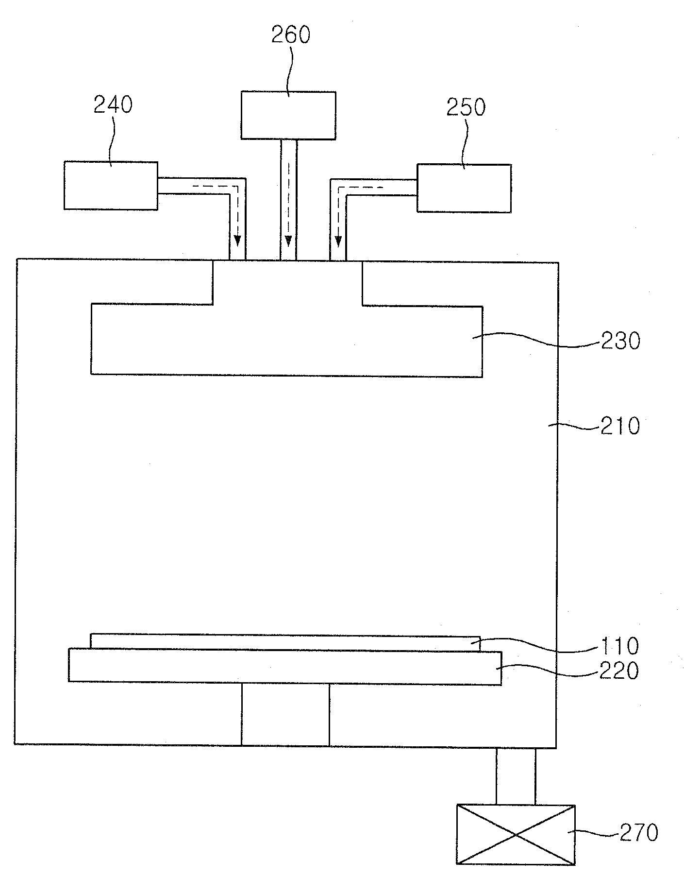
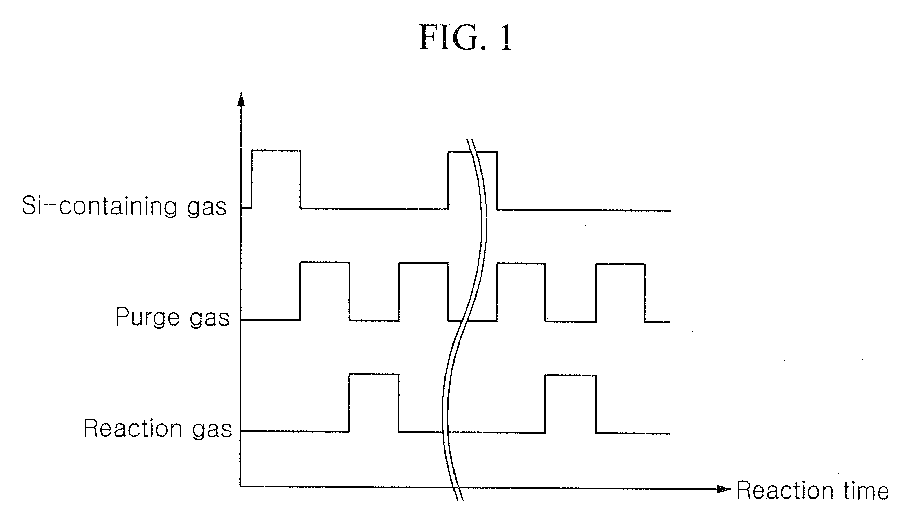
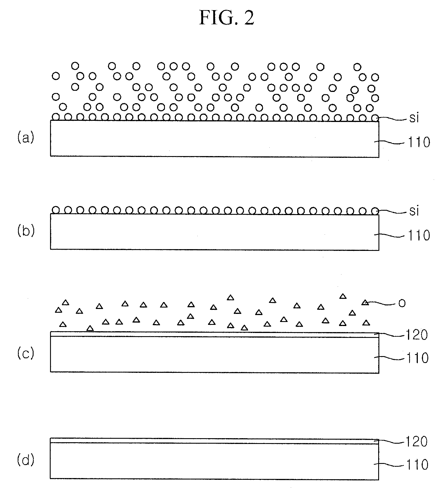
[0028]FIG. 1 is a process flowchart illustrating an oxide film forming method according to a first embodiment of the present invention, FIG. 2 is a schematic cross sectional view illustrating the oxide film forming method according to the first embodiment, and FIG. 3 is a cross sectional view of an oxide deposition apparatus according to the first embodiment.

[0029]Referring to FIGS. 1 to 3, a semiconductor substrate 110 is placed on a substrate mounting unit 220 in a chamber 210. A sili...


PUM

PropertyMeasurementUnit
temperatureaaaaaaaaaa
thicknessaaaaaaaaaa
temperatureaaaaaaaaaa

Abstract

The present invention relates to an oxide film forming method and an oxide deposition apparatus, which make it possible to form an oxide film at a low temperature of 350° C. or less by respectively supplying a silicon-containing gas including at least one of SiH4, Si2H6, Si3H8, TEOS, DCS, HCD and TSA, a purge gas, and a reaction gas including at least one of O2, N2O, O3, H20 and H2O2 into a reaction space continuously and simultaneously while rotating gas injector, and to form an oxide film with a uniform thickness along a step of a lower structure with a micro-pattern since step coverage is improved due to an atomic layer deposition process.

Description

[0001]This application claims priority to Korean Patent application No. 10-2006-0031292, filed on Apr. 6, 2006, and all the benefits accruing therefrom under 35 U.S.C. 119, the contents of which are herein incorporated by reference in its entirety.BACKGROUND OF THE INVENTION[0002]1. Field of the Invention[0003]The present invention relates to a method of forming an oxide film and an oxide deposition apparatus, and more particularly, to a method of forming a silicon oxide film through an atomic layer deposition (ALD) process using any one of SiH4, Si2H6, Si3H8, tetraethylorthosilicate (TEOS), dichlorosilane (DCS), hexachlorosilane (HCD) and trisilylamine (TSA), and an oxide deposition apparatus.[0004]2. Description of the Related Art[0005]In recent, since the line width of a semiconductor device is micronized (into 100 nm or less), a semiconductor substrate is enlarged, a deposited thin film is micronized and multi-layered, the uniform thickness and high step coverage of an oxide fil...

Claims


Application Information

Patent Timeline
Patent Type & Authority Applications(United States)
IPC IPC(8): C23C16/00C23F1/00
CPCC23C16/45551C23C16/402H01L21/0228H01L21/02164H01L21/02208H01L21/02274C23C16/45542C23C16/45553
Inventor LEE, JIN HOHAN, YOUNG KIKWAK, JAE CHAN
Owner JUSUNG ENG
Learn More