Plasma display panel and flat panel display device including the same

Inactive Publication Date: 2007-10-04
SAMSUNG SDI CO LTD
View PDF3 Cites 2 Cited by
  • Summary
  • Abstract
  • Description
  • Claims
  • Application Information

AI Technical Summary

Benefits of technology

[0012]The present embodiments provide a plasma display panel which has a low driving voltage and improved light emitting efficiency.
[0013]The present embodiments also provide a flat panel display including the plasma display panel having low driving voltage and improved light emitting efficiency.

Problems solved by technology

However, the plasma display panel 100 has a high driving voltage and a low light emitting efficiency.

Method used


Image

  • Plasma display panel and flat panel display device including the same
  • Plasma display panel and flat panel display device including the same
  • Plasma display panel and flat panel display device including the same

Examples


Embodiment Construction

[0034]Hereinafter, the present embodiments will be described more fully with reference to the accompanying drawings, in which exemplary embodiments are shown.

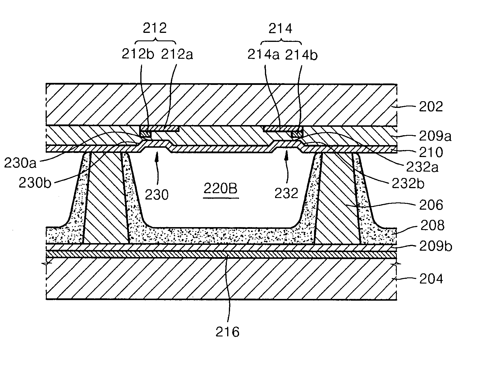
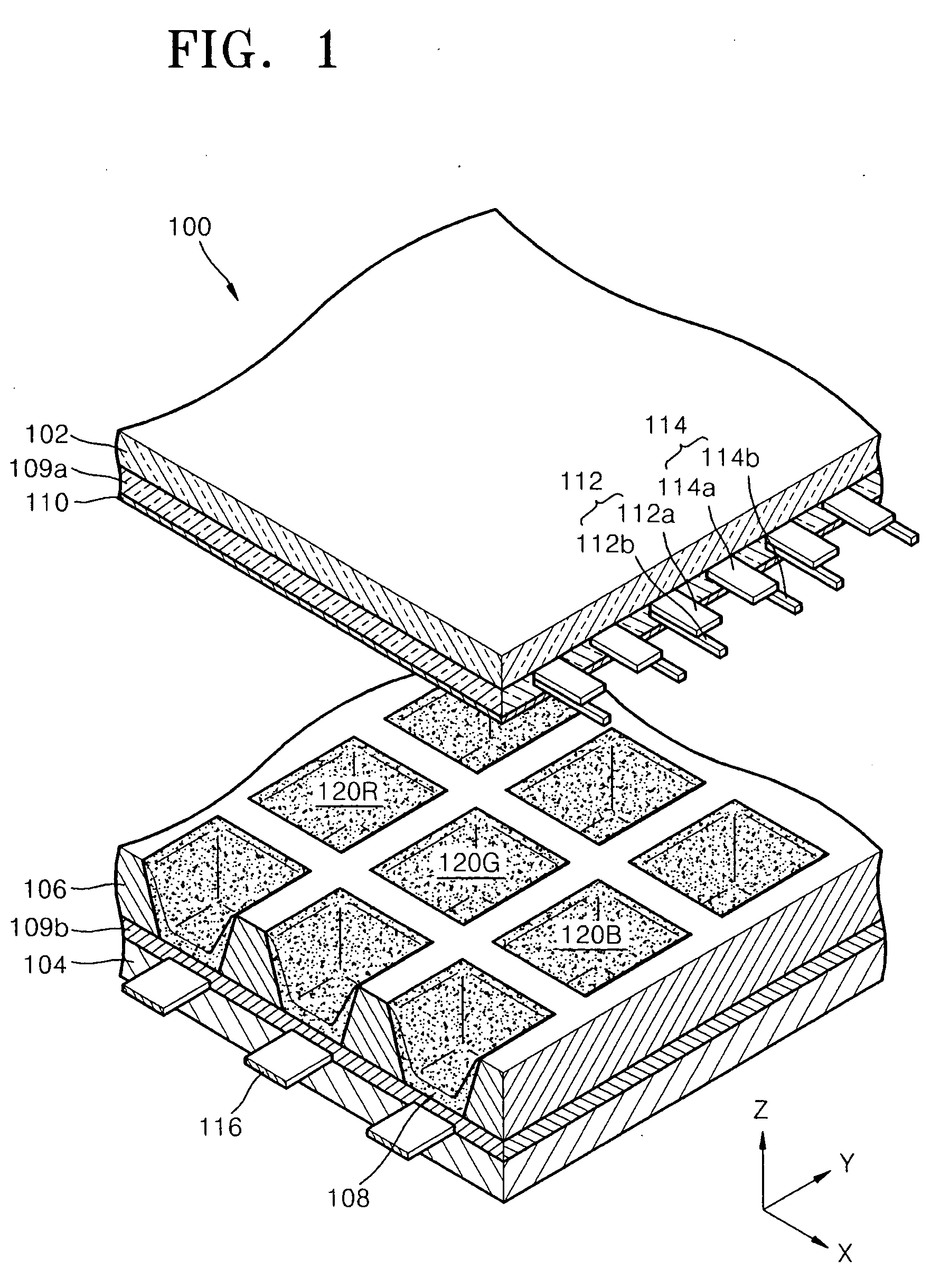
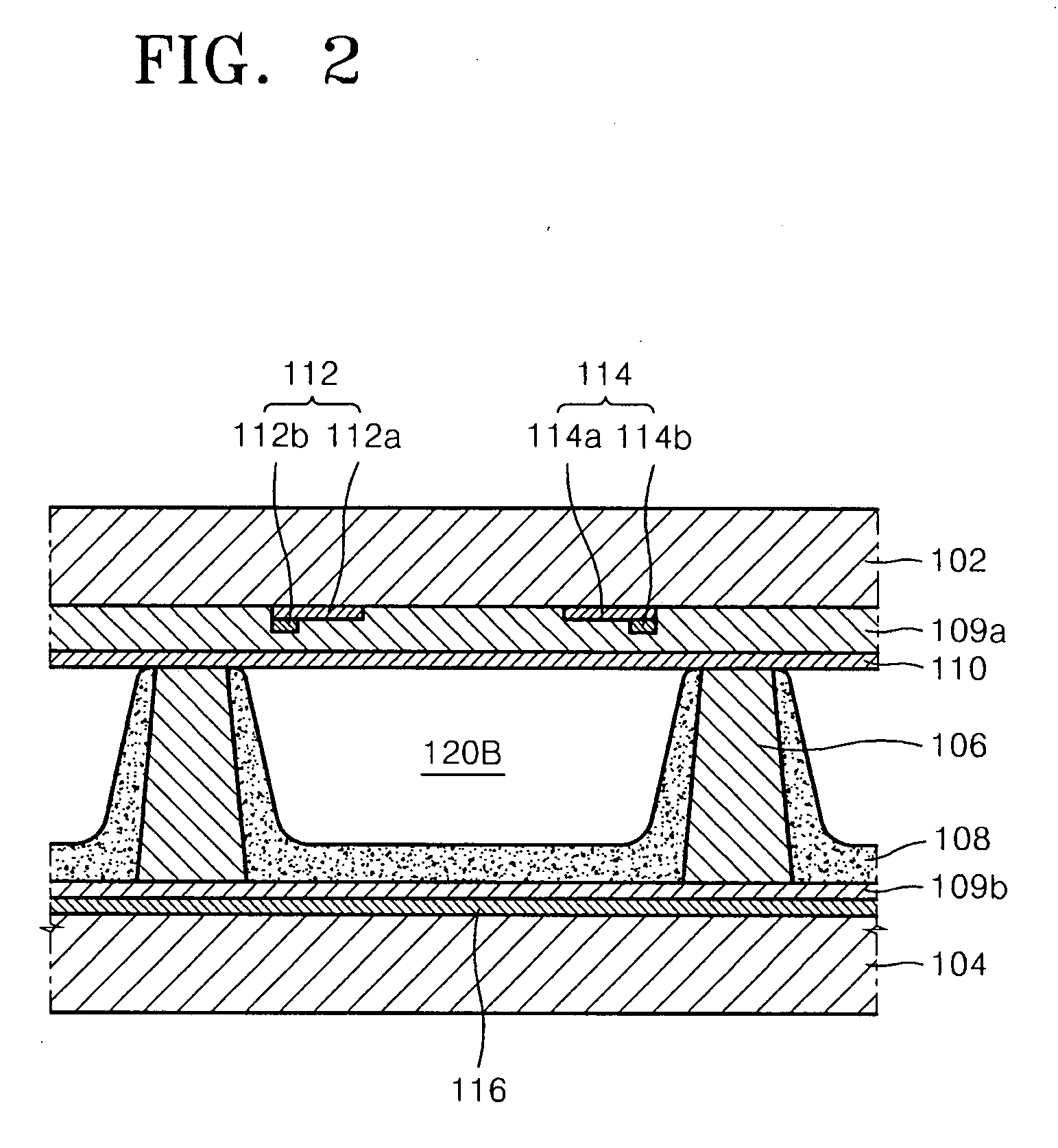
[0035]FIG. 3 is an exploded perspective view of a plasma display panel 200 including grooves according to one embodiment, FIG. 4 is a cross-sectional view of the structure of a discharge cell 220B in the plasma display panel illustrated in FIG. 3, as seen from an X-Z plane direction, FIG. 5 is a cross-sectional view of an upper plate from the cross-sectional view of the plasma display panel illustrated in FIG. 4, and FIG. 6 is a transparent view of the plasma display panel 200 illustrated in FIG. 3, as seen from a Z direction in order to show sustain electrodes 212 and 214, discharge cells 220R, 220G, and 220B, and grooves 230 and 232 illustrated in FIG. 3.

[0036]Referring to FIG. 3, the plasma display panel 200 includes an upper plate and a lower plate combined parallel to the upper plate. The upper plate includes a first subst...


PUM


Abstract

Provided is a plasma display panel including a first substrate and a second substrate facing each other, barrier ribs disposed between the first and second substrates and defining a plurality of discharge cells, a pair of sustain electrodes spaced apart from each other on the first substrate facing the second substrate, and each comprising an X electrode and an Y electrode, phosphor substances emitting red, green, and blue light, each color of light formed in the plurality of discharge cells, and a first dielectric layer covering the pair of sustain electrodes and comprising at least two corresponding grooves at each discharge cell, wherein an interval between the X electrode and the Y electrode is larger than the height of the barrier ribs, and an interval between the grooves in the discharge cell comprising the phosphor substance emitting light of one color is different from an interval between the grooves in another discharge cell comprising the phosphor substance emitting light of another color.

Description

CROSS-REFERENCE TO RELATED PATENT APPLICATION[0001]This application claims the benefit of Korean Patent Application No. 10-2006-0029115, filed on Mar. 30, 2006, in the Korean Intellectual Property Office, the disclosure of which is incorporated herein in its entirety by reference.BACKGROUND OF THE INVENTION[0002]1. Field of the Invention[0003]The present embodiments relate to a plasma display panel and a flat panel display, and more particularly, to a plasma display panel having an improved light emitting efficiency.[0004]2. Description of the Related Art[0005]Plasma display devices including a plasma display panels have come into the spotlight as large flat panel display devices. The plasma display device displays an image using visible rays which are generated while vacuum ultraviolet (VUV) radiation, generated by encapsulating discharge gas between two substrates of the plasma display panel including a plurality of electrodes and applying a discharge voltage, excites a phosphor s...

Claims


Application Information

Patent Timeline
IPC IPC(8): H01J17/49
CPCH01J11/12H01J2211/326H01J11/38H01J11/32H01J11/24H01J11/40
Inventor SOH, HYUNKIM, SE-JONGKIM, YUN-HEEKIM, HYUN
Owner SAMSUNG SDI CO LTD
Why Eureka
Try Eureka