Well servicing methods and systems

a technology for oil and gas wells and wells, applied in the direction of drilling casings, drilling pipes, borehole/well accessories, etc., can solve the problems of affecting the operation of monitoring operations, affecting the monitoring and job optimization, and affecting the flow of water

Inactive Publication Date: 2007-10-04
SCHLUMBERGER TECH CORP
View PDF46 Cites 72 Cited by
  • Summary
  • Abstract
  • Description
  • Claims
  • Application Information

AI Technical Summary

Benefits of technology

[0012](b) using the treatment fluid for propelling the communication line into the wellbore without significant damage to the communication line.
[0022]Systems within this aspect of the invention include those wherein the communication line is selected from optical fibers, micro-wires, and the like, and wherein the well control stack may be selected from a blowout preventer (BOP), stuffing box, lubricator, and functional equivalents thereof. Systems of this aspect of the invention reduce or eliminate bending that may cause fatigue and ultimate failure of the communication line. Systems may include means for collecting wellbore data, and these means may be part of the hub of the reel spool. Systems of this aspect of the invention reduce the number of components and pieces of equipment required and the complexity of the service setup. This should also reduce the amount of time required for rigging up and rigging down the system.
[0026]Systems of this aspect of the invention include those wherein a drive mechanism for the reel is also located within the housing, as well as a data interface. As used herein the phrase “fluidly connected” means the housing may be temporarily or permanently, but in any case securely, attached to the wellhead by means such as flanges, welds, clamps, and the like, as along as the mechanism of attachment allows wellhead pressure to be maintained in the housing at least long enough for the communication line to be un-spooled to a usable depth and / or location in the wellbore, and re-spooled, if desired. The pressure containment housing should have no fluid leak paths and should require no or minimal pressure testing. Power to turn the reel may be delivered magnetically though a non-magnetic housing wall or portion of wall, for example using a magnetic coupling. Thus an electrical or hydraulic motor may turn the reel from outside the housing without having to penetrate a wall of the housing. In system embodiments wherein the communication line is an optical fiber, the optical signal may be diffused (to improve contamination tolerance) at the optical connector device, passed from a rotating hub of the reel to a diffused optical connector which refocuses the optical signal to the diameter of the optical fiber. The optical fiber would then be passed through an optical pressure bulkhead in the housing wall and be available outside the housing. This may be a full duplex arrangement, wherein light beams may travel into and out of the wellbore.
[0030]Advantages of the systems and methods of the invention include compactness and lightweight, with no need for a truck to log a well; less trained or less skilled operators may be needed; low power requirements for running in hole and pulling out of hole; easier well control, since no BOP, stripper, lubricator, or stuffing box need be used. Systems of the invention may be dressed in the yard and be ready to be connected on the wellhead more quickly, and no slip ring or rotary collector is required. Low cost deployment of optical fiber and micro-wire should be realistic, and stringent and expensive intrinsic safety requirements, such as electrical codes in hazardous areas, may be eliminated.

Problems solved by technology

Some fluids are designed to increase the flow of hydrocarbon, others impede the flow of water or build-up of scale.
This monitoring operation is non-trivial, however, because the fluids are typically highly non-Newtonian with pressure-drops along the completion that are difficult to determine in advance.
The stimulation fluid may include solid particles, such as proppant, which further complicates the monitoring and job optimization.
Unfortunately, there may be disadvantages to having the coiled tubing in the wellbore during the stimulation treatment.
The annular space around the tubing may be less than one or two inches, which increases the friction pressure when the fluid is pumped and so increases the surface horsepower required to do the job, compared with pumping straight into the wellbore—a process known as bull-heading.
These fluids may also damage the coiled tubing leading to high maintenance costs for the service.
Another disadvantage is the large apparatus needed to convey the coiled tubing into the wellbore such as disclosed, for example in U.S. Pat. No. 6,273,188.
In many cases, the cost of such systems may be prohibitive compared to the benefit of the real-time downhole data, so the industry has come to accept taking surface measurements and making inferences of the downhole state.

Method used


Image

  • Well servicing methods and systems
  • Well servicing methods and systems
  • Well servicing methods and systems

Examples


embodiment 200

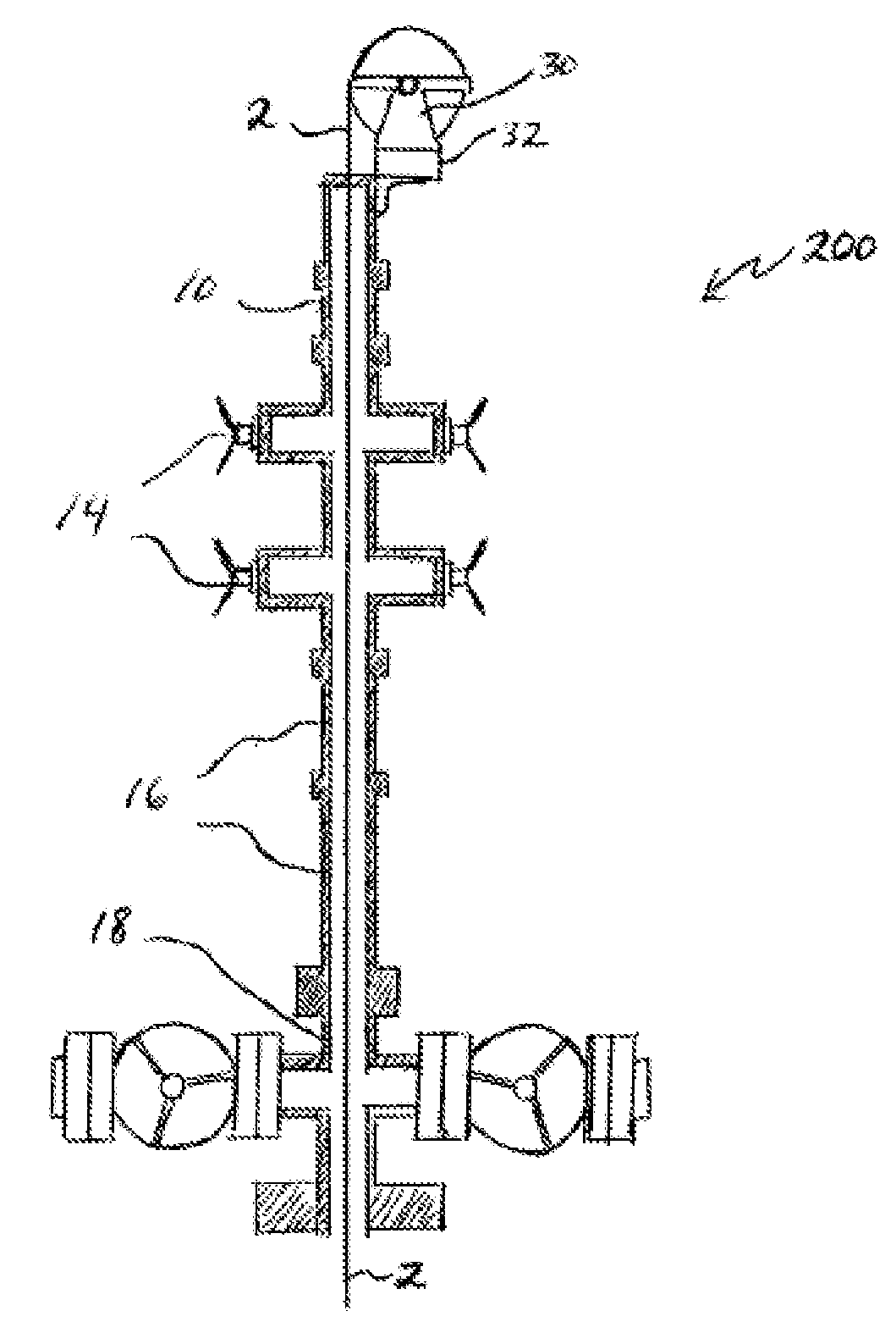
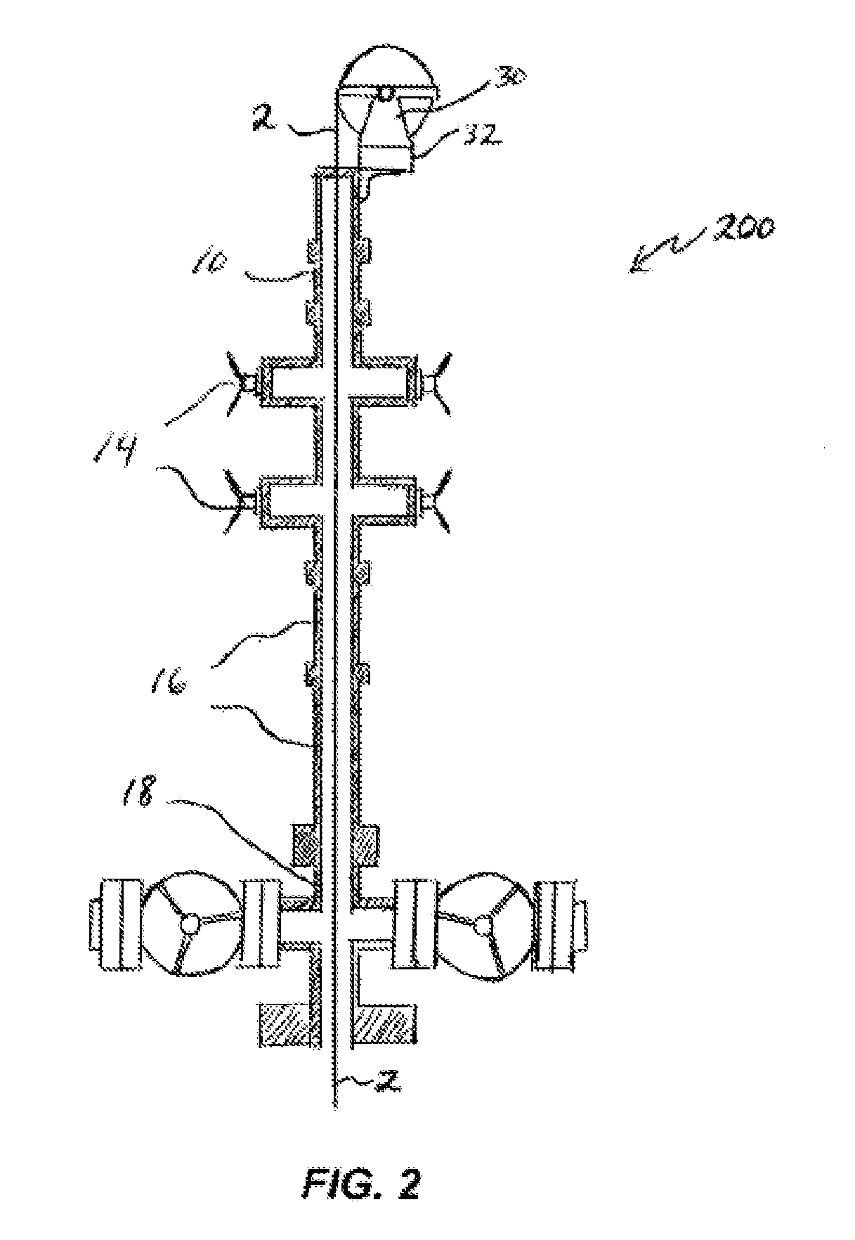
[0061]FIG. 2 is a schematic partial cross-sectional view of one embodiment, 200, of the invention. Communication line 2 is deployed from a communication line deployment reel 30 mounted directly via a bracket 32 onto stuffing box or lubricator 10. Alternatively, reel 30 could be mounted directly to the top-most BOP 14. This embodiment and its functional variations eliminate or greatly reduce bends in communication line 2 that may result in fatigue and ultimate failure of communication line 2. A drive mechanism (not shown) for reel 30 may be mounted directly on the well control stack, for example on lubricator 10, or it could be located on some other surface or platform. Data retrieved from the wellbore may be collected at the hub of the spool of reel 30. Embodiment 200 and its functional and structural equivalents may reduce rig up and rig down time, as well as require fewer pieces of equipment, and is less complex to implement compared to systems such as depicted in FIG. 1.

[0062]FIG...

embodiment 400

[0065]FIG. 4 is a schematic process information flow sheet of a method embodiment 400 that may be useful in understanding certain features of the invention. Box 60 represents a starting point for injection of a first treatment fluid, which may be a brine or other fluid. During this injection of brine, start unspooling the communication line with the first fluid, and obtain temperature and pressure data while unspooling the communication line, as illustrated at box 62. Once the communication line is at a first depth, data at that specific depth may be obtained, as depicted at box 64. Then a second treatment fluid may be injected, at box 66, moving the communication line to a new depth while obtaining pressure and temperature data during this second movement of the communication line. After reaching this second depth, a second set of temperature and pressure data may be obtained at this second depth, as illustrated at box 68. As a final step 70, a third treatment fluid might be inject...


PUM


Abstract

Well servicing methods and systems are described, in one embodiment comprising a pressure containment housing fluidly connected directly to a wellhead of a wellbore, and a reel positioned inside the housing on which is spooled a communication line. One method comprises introducing the communication line into the pressurized wellbore without a well control stack, the communication line being introduced and driven into the wellbore by controlling a reel, the reel being internal to a pressurized housing removably connected directly to a wellhead of the wellbore. Fluid flow may move the communication line to a desired location in the wellbore. This abstract allows a searcher or other reader to quickly ascertain the subject matter of the disclosure. It may not be used to interpret or limit the scope or meaning of the claims.

Description

BACKGROUND OF THE INVENTION[0001]1. Field of Invention[0002]The present invention relates generally to the field of well servicing of oil and gas wells, and more particularly to methods and systems useful in well servicing operations such as well stimulation.[0003]2. Related Art[0004]The production of hydrocarbon from reservoirs requires permanently installed wellbores in the ground composed of a multiplicity of largely tubular structures referred to as the wellbore completion. Increasing the production of hydrocarbon typically requires the pumping of a fluid down the wellbore and into the reservoir. Some fluids are designed to increase the flow of hydrocarbon, others impede the flow of water or build-up of scale. Measurements may be made of fluid flow-rate, pressure, etc, at the surface to optimize the treatment. This monitoring operation is non-trivial, however, because the fluids are typically highly non-Newtonian with pressure-drops along the completion that are difficult to det...

Claims


Application Information

Patent Timeline
Patent Type & Authority Applications(United States)
IPC IPC(8): E21B19/00
CPCE21B33/072E21B23/14E21B19/22E21B33/05
Inventor LOVELL, JOHN R.ADNAN, SARMADAYOUB, JOSEPH A.GAY, MICHAEL G.
Owner SCHLUMBERGER TECH CORP
Why Eureka
Try Eureka