
Vertical injection molding machine

Active Publication Date: 2007-09-27
TOYO MACH & METAL CO LTD
View PDF2 Cites 6 Cited by
  • Summary
  • Abstract
  • Description
  • Claims
  • Application Information

AI Technical Summary

Benefits of technology

[0014] According to the first aspect of the invention, the slide resistance of the sliding portion of the turntable revolved during operation of the vertical injection molding machine can be maintained substantially constant, and thus the turntable can be stopped at predetermined positions. Further, the control means resets the pulses recorded in the encoder at a timing at which the number of revolutions of the servomotor is an integer and the number of revolutions of the turntable is also an integer. Therefore, the error of pulses caused by resetting the pulse counts per a single revolution of the turntable is no longer accumulated, and the position of the turntable can be determined accurately without error even when the turntable is revolved repeatedly for many times to the same direction.

Problems solved by technology

However, since according to the vertical injection molding machine of FIG. 10, the stopper pin is repeatedly pressed against the stopper for each molding process by the revolution of the turntable in both directions, the contact portions of the stopper pin and the stopper are both worn.
When the vertical injection molding machine is operated for a long period of time, the components such as the stopper pin used for positioning are worn away, making it difficult to stop the lower molds at predetermined positions.
Moreover, if the vertical injection molding machine is continuously operated in the state in which the contact portions are worn away, the molds subjected to clamping are displaced from the predetermined positions, and in some cases, the molds may even be damaged during clamping.
Further, since it is necessary to replace worn components such as the stopper pin and the stopper periodically, the replacement of worn components requires much time and work, and the operation of the molding machine must be interrupted each time the component is to be replaced, so that the manufacturing costs of molded products are increased in vertical injection molding machines producing molded products having insert components made of metal or the like integrally molded with resin.
Further, when the stopper pin collides against the stopper, not only the stopper pin and the stopper but also the drive system of the turntable may be damaged.
Furthermore, according to the example illustrated in FIG. 10, the turntable is stopped by having the stopper pin press against the stopper, but if such structure is not adopted and the revolving turntable is stopped only by the control of the servomotor being the drive source of the turntable, the turntable not only fails to stop within a predetermined range but also the stop position is displaced greatly along with the passing of turntable operation time.
When the sliding portions are fed with sufficient amount of lubricant and the sliding conditions thereof are good, the rotational resistance is small, but when the sliding portions lack lubricant and the sliding conditions thereof are poor, the rotational resistance is increased correspondingly.
However, in a device that does not utilize the stopper, the number of pulses of the encoder will increase continuously and finally exceed a maximum number of pulses countable by the encoder if the turntable is continuously revolved in the same direction, and the accurate position of the turntable, that is, the angle of the turntable, can no longer be detected.
In order to prevent this problem from occurring, it is necessary to reset the count before the number of pulses exceeds the maximum number of pulses countable by the encoder, but it is difficult to detect the position or angle of the turntable accurately without a stopper and to reset the count.

Method used


Image

  • Vertical injection molding machine
  • Vertical injection molding machine
  • Vertical injection molding machine

Examples


embodiment 1

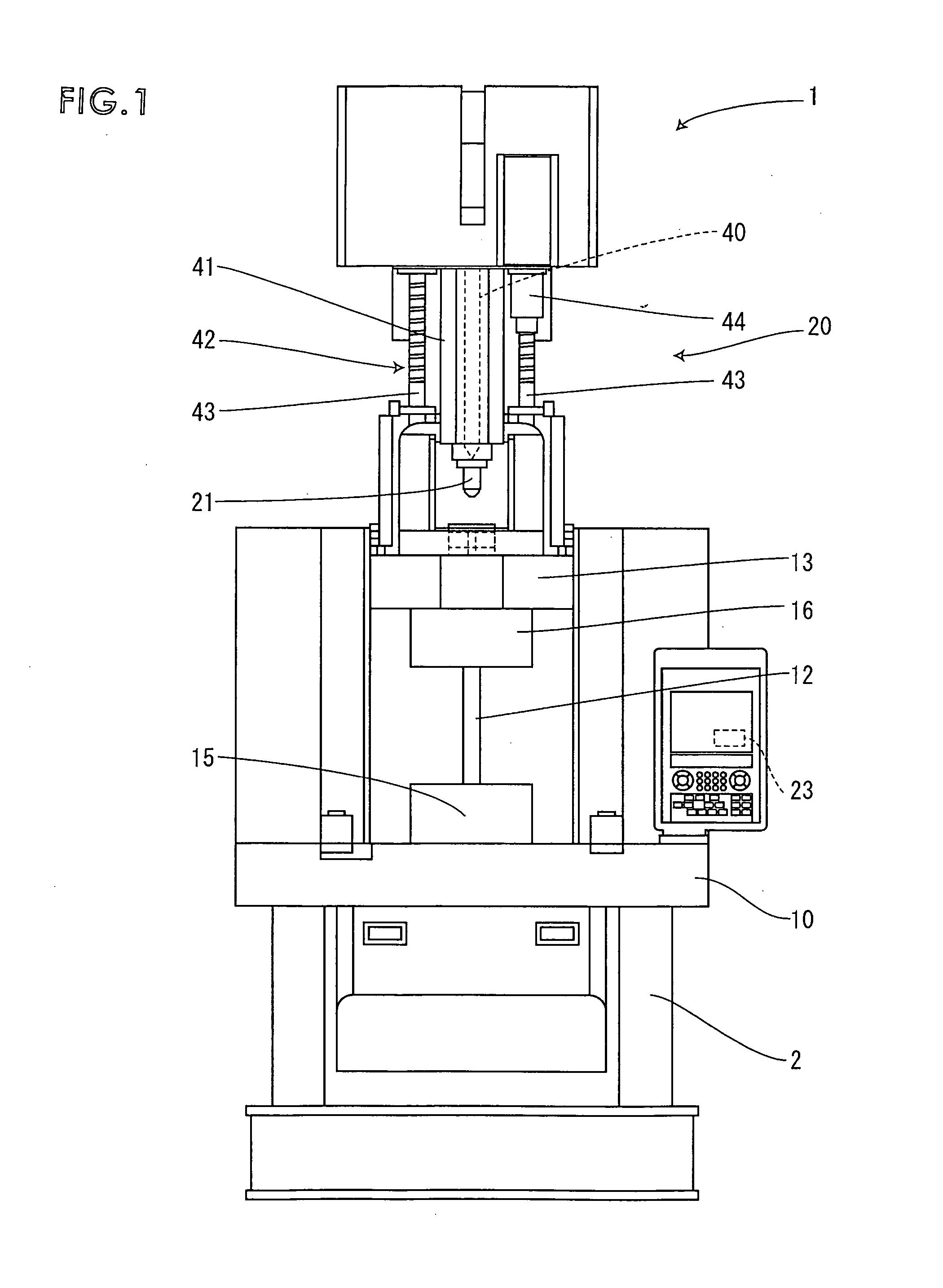
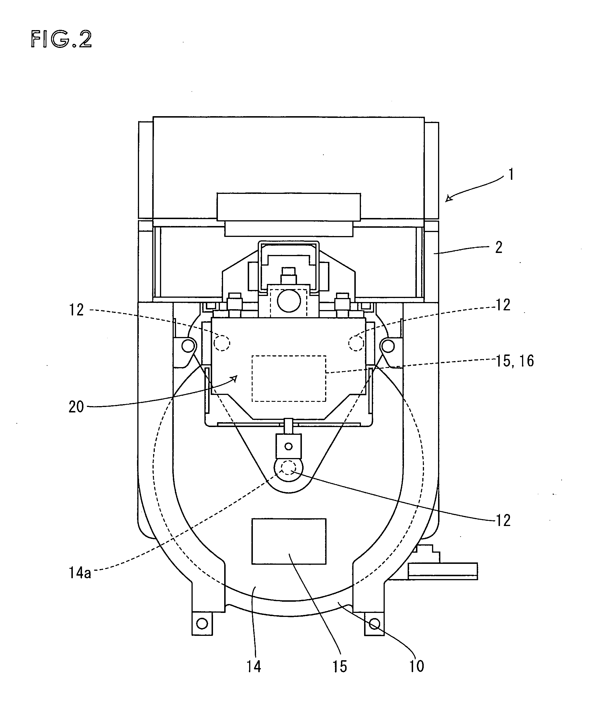
[0026]FIG. 1 is a front view of a vertical injection molding machine according to embodiment 1, FIG. 2 is a plan view of the vertical injection molding machine, FIG. 3 is a cross-sectional view showing the relevant portion of the vertical injection molding machine from above, FIG. 4 is a cross-sectional view showing the relevant portion of the vertical injection molding machine, and FIG. 5 is a graph showing the stopping accuracy of the turntable.

[0027] The vertical injection molding machine 1 illustrated in FIG. 1 is for forming a molded member by integrally molding an insert component such as a metal component with resin by opening and closing a mold in the vertical direction. An intermediate retention plate 10 is fixed to a machine base 2 of the vertical injection molding machine 1, and an upper retention plate 13 is placed above the intermediate plate with a space therebetween, and as shown in FIG. 4, three cylindrical tie bars 12 erected to the upper and lower retention plates...

embodiment 2

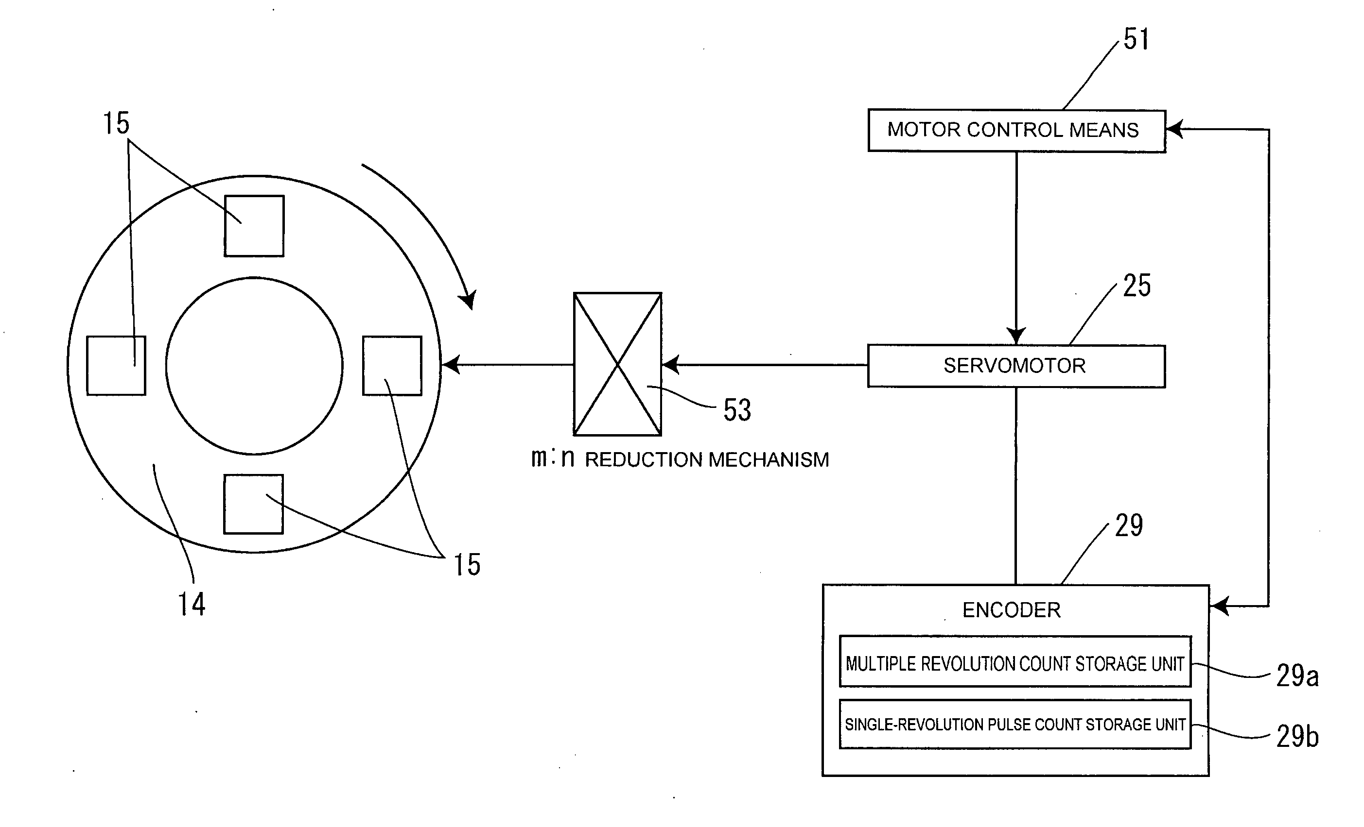
[0045]FIGS. 6 through 9 illustrate a second embodiment of the present invention, wherein FIG. 6 is a cross-sectional view showing the state in which the vertical injection molding machine is viewed from above, FIG. 7 is a block diagram showing the outline of the structure for revolving the turntable, FIG. 8 is a comparison chart showing the relationship between the number of revolutions of the servomotor, the encoder pulses and the number of revolutions of the turntable, and FIG. 9 is an example of the screen for setting up the table revolution. The table revolution setup screen of FIG. 9 illustrates one example of a screen which is a display means of a molding machine control means not shown for controlling the vertical injection molding machine 1 connected to the motor control means 51. The angle (deg) of the table is shown at the center of the table on the screen. This is a screen for displaying the angle (deg) of the turntable 14 corresponding to the revolution of the turntable ...


PUM

PropertyMeasurementUnit
Electrical resistanceaaaaaaaaaa

Abstract

The invention provides a vertical injection molding machine capable of periodically feeding lubricant to sliding portions of the turntable to maintain a substantially constant turntable slide resistance and also capable of determining the position of the repeatedly revolving turntable. During operation of a vertical injection molding machine 1, lubricant is periodically fed from a pump 30 to slide portions S of the revolving turntable 14 so as to maintain the slide resistance of the sliding portions S substantially constant. Further, a motor control means 51 resets the count of pulses output from an encoder 29 at a timing at which the number of revolutions of a servomotor 25 and the number of revolutions of the turntable 14 are integers, so that it is possible to prevent pulse errors from accumulating even when the turntable 14 is revolved many times in the same direction.

Description

[0001] The present application is based on and claims priority of Japanese patent application No. 2005-113474 filed on Apr. 11, 2005, and Japanese patent application No. 2006-052008 filed on Feb. 28, 2006, the entire contents of which are hereby incorporated by reference. BACKGROUND OF THE INVENTION [0002] 1. Field of the Invention [0003] The present invention relates to a vertical injection molding machine for molding a product by clamping and releasing molds in the vertical direction, and more specifically, relates to a vertical injection molding machine having a turntable to which molds are mounted. [0004] 2. Description of the Related Art [0005] Heretofore, a so-called two-station type vertical injection molding machine has been used, wherein two lower molds mounted on a turntable are moved to positions capable of being clamped with a single upper mold by the revolving motion of the turntable, and the molds are clamped in the vertical direction. According to this so-called two-s...

Claims


Application Information

Patent Timeline
IPC IPC(8): B29C45/76
CPCB29C45/062B29C45/80B29C2945/76224B29C2945/76093B29C45/83
Inventor KUNIMATSU, KIYOSHIKANDA, YUICHIRO
Owner TOYO MACH & METAL CO LTD
Learn More