
Backlight module

a backlight module and backlight technology, applied in the field of backlight modules, can solve the problems of liquid crystal display modules being defective, conventional backlight modules may become defective,

Inactive Publication Date: 2007-09-27
CHUNGHWA PICTURE TUBES LTD
View PDF1 Cites 34 Cited by
  • Summary
  • Abstract
  • Description
  • Claims
  • Application Information

AI Technical Summary

Benefits of technology

[0009]It is an aspect of the present invention to provide a backlight module, which can prevent the optical film thereof from being warped when the ambient temperature varies.
[0010]It is another aspect of the present invention to provide a liquid crystal display module, which can prevent the optical film from being pressed by the backlight module when the ambient temperature varies.

Problems solved by technology

However, the conventional backlight module may become defective when the ambient temperature varies.
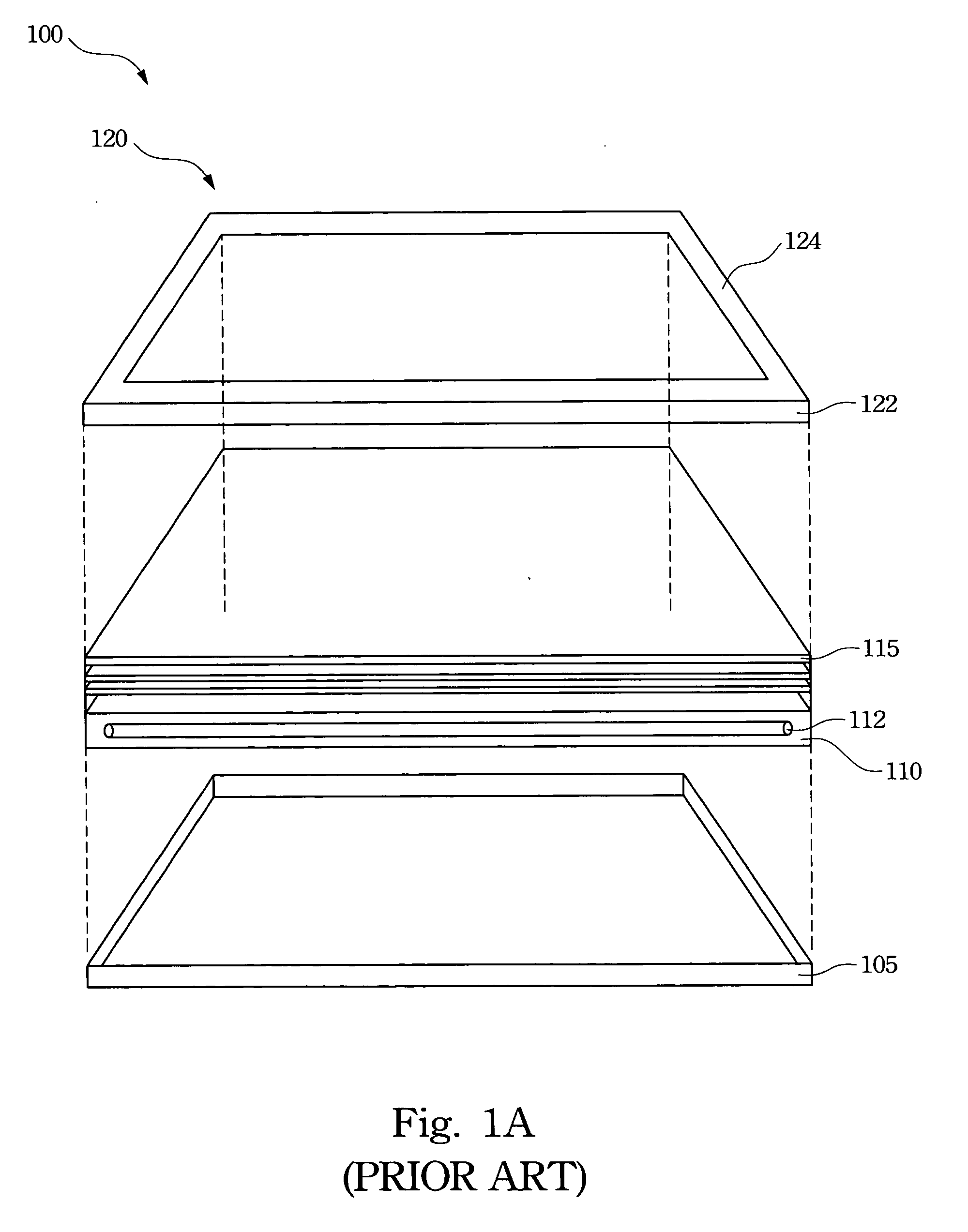
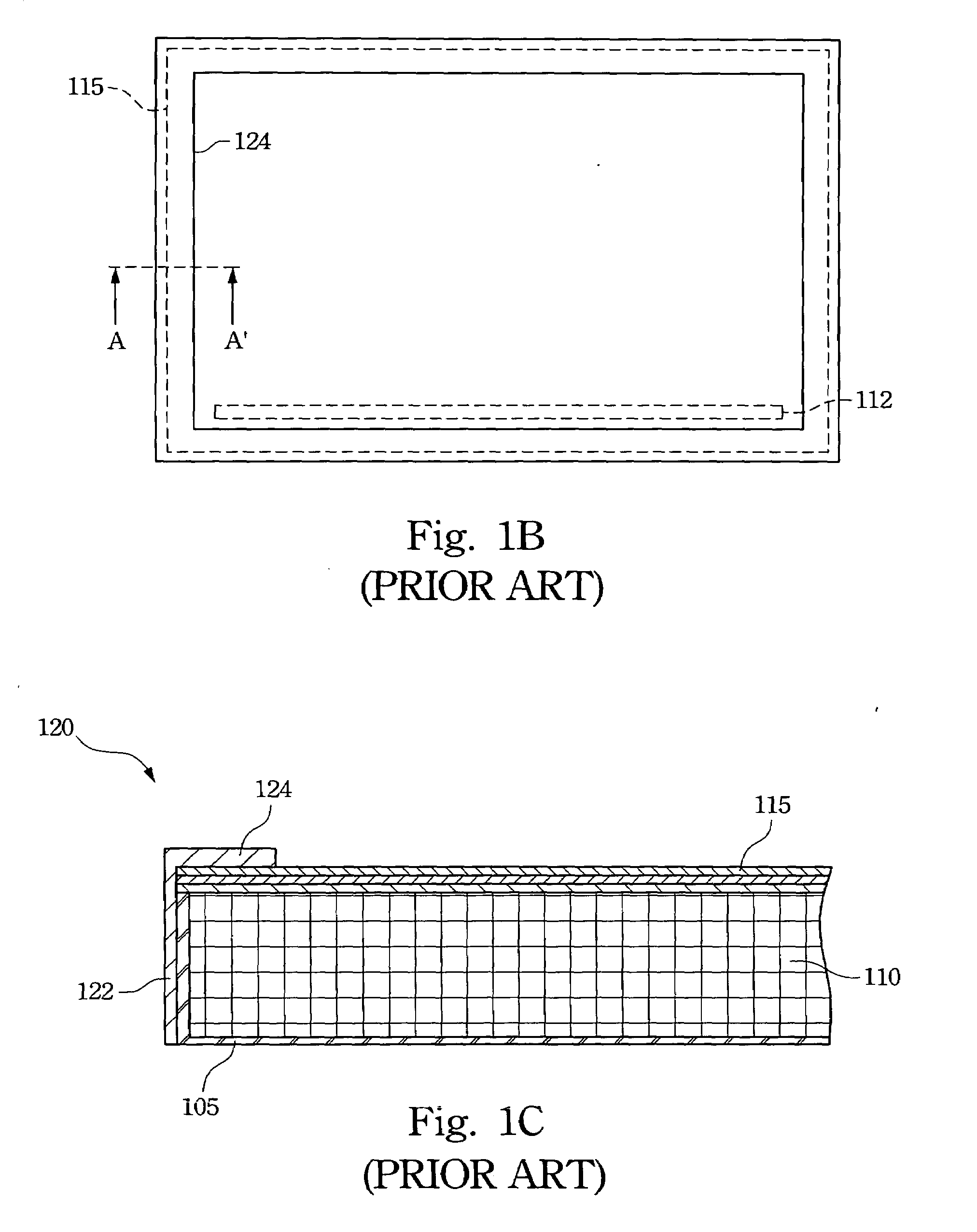
A display problem of the liquid crystal display module thus arises when the ambient temperature varies, because the optical film 115 becomes warped and presses the polarizer of the liquid crystal display module.
Accordingly, providing a backlight module that can prevent the liquid crystal display module from being defective when the temperature varies is an issue of great consequence.

Method used


Image

  • Backlight module
  • Backlight module
  • Backlight module

Examples


Embodiment Construction

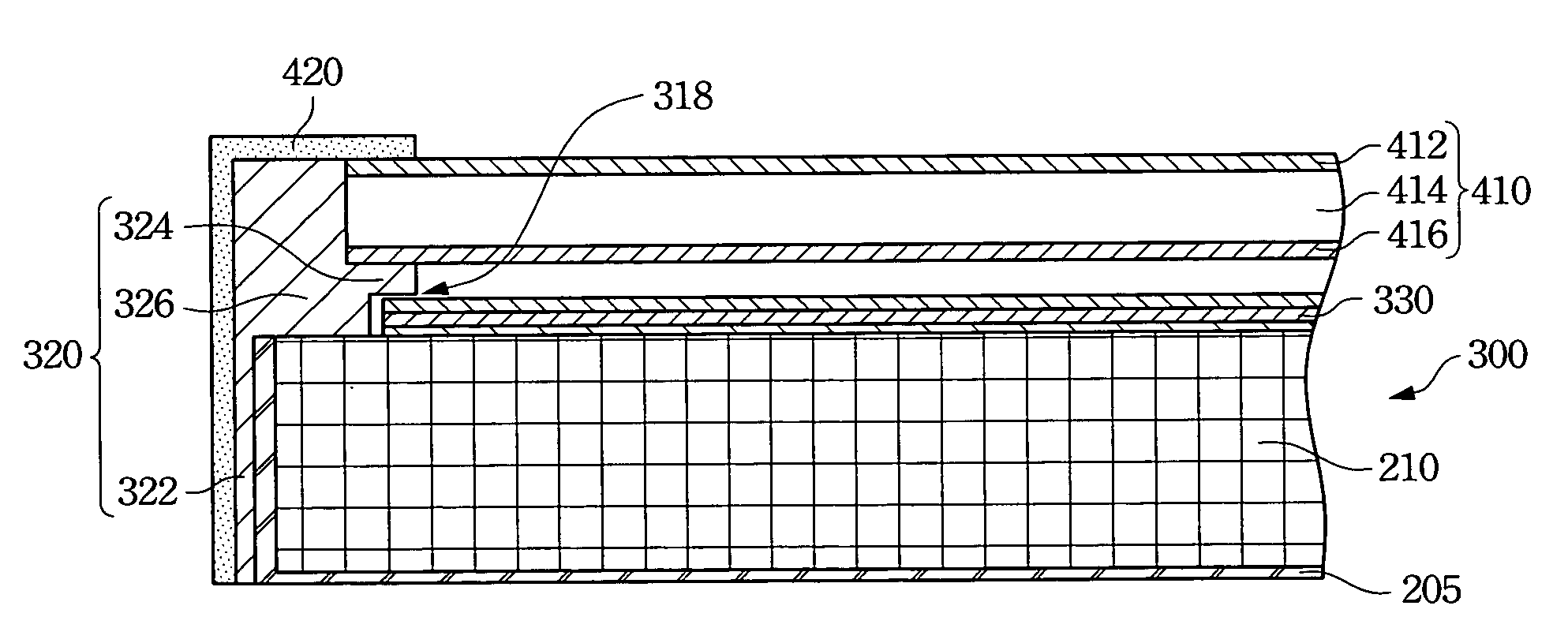
[0025]FIG. 2A is a top view of one preferred embodiment of the present invention. FIG. 2B illustrates the cross-sectional view of the B-B′ line in FIG. 2A. In FIG. A and FIG. B, a backlight module 200 includes a back cover 205, an optical plate 210, at least one light source 215, a mold frame 220 and at least one optical film 230. The optical plate 210 disposed on the back cover 205 may be a light guide plate or a diffuser plate. The back cover 205 may be made of metal, such as aluminum. The optical plate 210 may be made of Polymethyl methacrylate (PMMA). The optical plate 210 is used to uniformly guide the light emitted from the light source 215 to a light outlet surface 212 in order to improve the quality of the backlight module 200. The light source 215 may be a cold cathode fluorescent lamp (CCFL), a light emitting diode (LED) or an electroluminescent lamp (EL). The light source 215 is disposed adjacent to the optical plate 210. The light source 215 can be located at one lateral...


PUM


Abstract

A backlight module of a liquid crystal display is provided. The backlight module includes a back cover, an optical plate, at least one light source, a mold frame and at least one optical film. The optical plate is disposed on the back cover and the light source is disposed adjacent to the optical plate. The mold frame surrounding the back cover has a protruding structure. The protruding structure is located between a light outlet surface of the optical plate and a front frame of the mold frame to form a recess, so that the optical film can be disposed in the recess. The present invention also discloses a liquid crystal module including a backlight module and a liquid crystal panel. The liquid crystal panel is disposed on a mold frame of the backlight module.

Description

RELATED APPLICATIONS[0001]The present application is based on, and claims priority from, Taiwan Application Serial Number 95110153, filed Mar. 23, 2006, the disclosure of which is hereby incorporated by reference herein in its entirety.BACKGROUND[0002]1. Field of Invention[0003]The present invention relates to a backlight module, and more particularly, to a mold frame of the backlight module.[0004]2. Description of Related Art[0005]Since liquid crystal display (LCD) devices are non-emissive type display devices, they require external light sources to display the images. Generally, a backlight module is disposed behind a LCD panel to provide light to the LCD panel. The backlight module is an important component that greatly influences the display quality of the LCD device.[0006]FIG. 1A is a schematic, exploded view of a conventional backlight module. FIG. 1B is schematic, top view of the conventional backlight module in FIG. 1A. FIG. 1C is a cross-sectional view from the A-A line in ...

Claims


Application Information

Patent Timeline
IPC IPC(8): G02F1/1333
CPCG02B6/0088G02F1/133615G02F1/133608
Inventor HU, CHENG-CHUNG
Owner CHUNGHWA PICTURE TUBES LTD
Learn More