
Method and system for correlating radar position data with target identification data, and determining target position using round trip delay data

Active Publication Date: 2007-09-27
SAAB INC
View PDF13 Cites 12 Cited by
  • Summary
  • Abstract
  • Description
  • Claims
  • Application Information

AI Technical Summary

Benefits of technology

[0008]It is the object of the present invention to provide a method and system that overcomes the problems of the prior art by providing a high quality surface picture, including target identification data, using radar and a minimum number of transceivers, such as radar beacon transceivers. The method of the present invention uses radar data as the main source for accurate target localization. One or more transceivers provide target identification data and facilitate access to flight plan and other relevant data. Multiple transceivers provide the capability to overcome line of sight problems and help resolve any target location ambiguities that may be present in high traffic density airport surface scenarios. In addition, the availability of multiple transceivers allows the system to locate targets if the radar malfunctions or stops working. Even when multiple transceivers are employed, however, the overall number is substantially less than what would be required in a traditional multilateration system.
[0010]The method and system of the present invention as just described allows an airport that has a local radar capability to augment the radar position data with the target identification data that is typically available only from transceiver-based technologies, such as multilateration systems. As such, the airport can derive the identification-component value associated with transceiver-based systems without having to buy and maintain a multiple transceiver installation; one transceiver is all that is required to augment the radar.

Problems solved by technology

All of the aforementioned requirements drive up the cost of obtaining and maintaining an ASMGCS multilateration system.
While an ASMGCS radar system provides position data on all targets, an ASMGCS radar system does not provide any target identification data to facilitate interpretation of the surface movement picture and does not provide easy access to flight plan and other relevant data.

Method used


Image

  • Method and system for correlating radar position data with target identification data, and determining target position using round trip delay data
  • Method and system for correlating radar position data with target identification data, and determining target position using round trip delay data
  • Method and system for correlating radar position data with target identification data, and determining target position using round trip delay data

Examples


Embodiment Construction

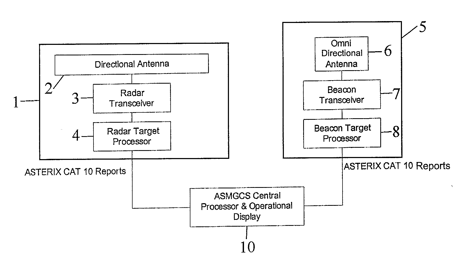
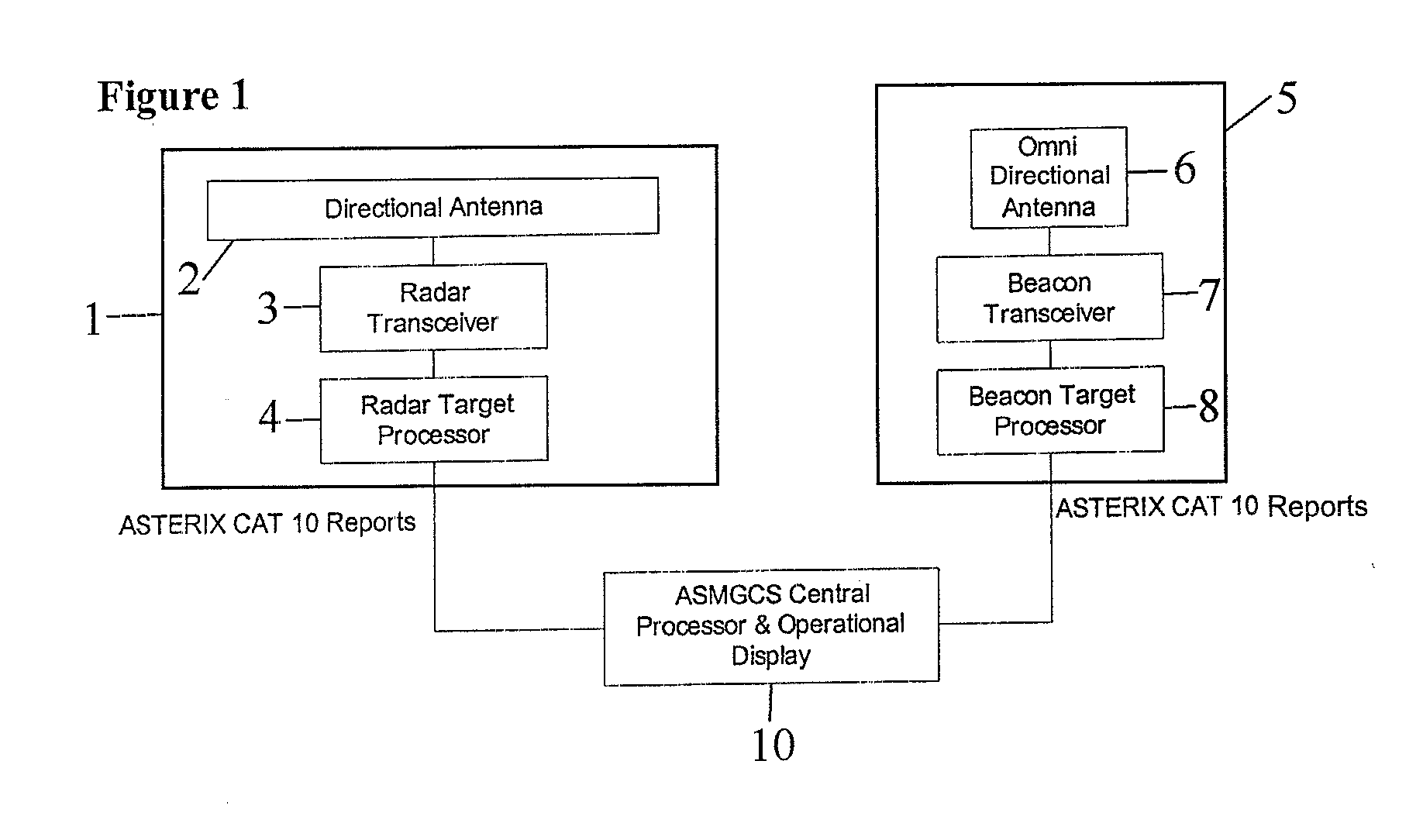
[0028]One embodiment of the method and system of the present invention includes an SMR and a single cooperative sensor. FIG. 1 shows a general block diagram of this embodiment, wherein the equipment configuration includes an SMR 1, a beacon sensor 5, a system central processor 10 and means for communicating between these components. The SMR 1 includes a directional antenna 2, a radar transceiver 3 and a radar target processor 4. The beacon sensor 5 includes an omni-directional antenna 6, a beacon transceiver 7 and a target processor 8. The omni-directional antenna 6 is located near the target area, for example, the airport surface movement area. For cost considerations, co-locating the beacon sensor 5 with the SMR 1 is preferable, but not required. The means for communicating may include a hardwired communications interface or a wireless communications link, such as a datalink, for example.

[0029]The SMR radar transceiver 3 sends radar video data to the radar target processor 4, whic...


PUM


Abstract

A method and system for using a single transceiver to correlate radar position data with target identification data. Two transceivers, operating in round trip delay mode, can be used to provide two possible positions for a given target when radar coverage is lost or unavailable. Three transceivers can be used to provide actual position of a given target using round trip delay data only.

Description

CROSS REFERENCE TO RELATED APPLICATIONS[0001]This application claims the benefit of U.S. Provisional Application No. 60 / 785,513, filed Mar. 24, 2006 and U.S. Provisional Application No. 60 / 801,011, filed May 17, 2006, the entireties of which are incorporated herein by reference.FIELD OF THE INVENTION[0002]The present invention relates to a method and system for correlating radar position data with target identification data, as well as a method and system for determining target position using round trip delay data.BACKGROUND OF THE INVENTION[0003]There are several known methods that can be used to provide localization data on surface targets. For example, a surface movement radar (SMR) will provide detection of all surface targets on the movement area of an airport. The radar technology used in an SMR is based on the transmission and reception of radio waves and reception of return echoes from all of the targets. A combination of the narrow beam antenna and highly precise measuremen...

Claims


Application Information

Patent Timeline
IPC IPC(8): G01S13/93
CPCG01S13/872G01S2013/916G01S13/91
Inventor PERL, ELYAHU
Owner SAAB INC
Learn More