
Multi-layer heating element

Inactive Publication Date: 2007-09-27
FEDERAL MOGUL WORLD WIDE
View PDF5 Cites 9 Cited by
  • Summary
  • Abstract
  • Description
  • Claims
  • Application Information

AI Technical Summary

Benefits of technology

[0009] The present invention relates to heating elements and, in particular, to heating elements for glow plugs and gas igniters as well as the method of manufacturing thereof. The heating element generally includes a first layer formed from or acting as an electrically insulative material and a second layer formed out of a electrically conductive material that is molded around portions of the first layer. By varying the geometric profile of the first layer and the geometric profile of an injection die, the thickness of the conductive layer may be varied along the length as well as around the circumference of the heating element to provide a desirable heating profile for a specific application. The molded profile of the first layer and the profile of a die in which the electrically conductive layer is molded allows for these geometric profiles and variations in the heating profile that are not available with the slip casting method. Furthermore, by molding the electrically conductive layer as a single piece extending between a first electrical connection and a second electrical connection prevents many of the problems with the prior art methods by removing discrete interfaces between layers and eliminating the electrical interface.

Problems solved by technology

One problem with sequential casting is that the geometric configuration of the heating element is generally limited to shapes that allow each progressive layer to be formed against the previous layer.
In the case of slip casting, the configuration of any layer is generally limited to a thin layer of fairly uniform thickness or a core that is substantially solid, but may be partially hollow due to piping which occurs as the cast material solidifies.
Another drawback to the style of glow plugs 2 illustrated in FIG. 1 is that the sequential layering creates discrete interfaces between layers and when the glow plug is cycled between cold and hot temperatures, failures may occur.
As the different layers expand and contract at different rates, stress may occur that may cause failure of the glow plug, commonly in the heating element of the glow plug.
Yet another drawback to the style of glow plugs 2 illustrated in FIG. 1 is that the electrical connection 9 between the conducting core 8 and the outer resistive layer 4 is in close proximity to the external surface of the glow plug 2 and may be subject to oxidation from the surrounding atmosphere during service.
Sufficient oxidation at the electrical connection 9 can degrade the electrical connection 9 by the formation of an electrically insulating oxide layer, or the formation of a porous layer having an interfacial porosity, to the point where current can no longer pass between the conducting core 8 and the resistive layer 4, resulting in a failure of the glow plug to heat when an electrical current is applied.
Yet another drawback to the style of glow plugs 2 illustrated in FIG. 1 is that the inconsistencies in the layer thickness and geometry created by the casting process leads to inconsistent resistance between manufacturing lots.
In addition, when the casting slip is removed, the newly cast surface remains wet for a short period of time, and this small amount of remaining liquid slip may form drips or runs that further contribute to non-uniform layer thickness.
Any of these factors may cause small variations in the layer thickness and the uniformity of the thickness of the layers which result in variations in the electrical resistance of the glow plugs and variances in the heating profile of the glow plug.

Method used


Image

  • Multi-layer heating element
  • Multi-layer heating element
  • Multi-layer heating element

Examples


Embodiment Construction

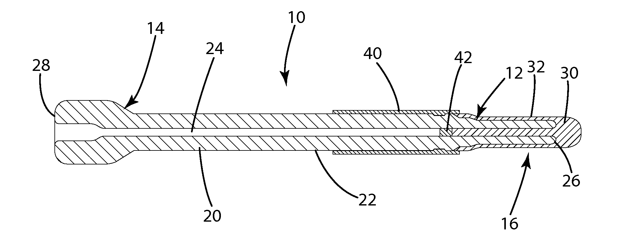
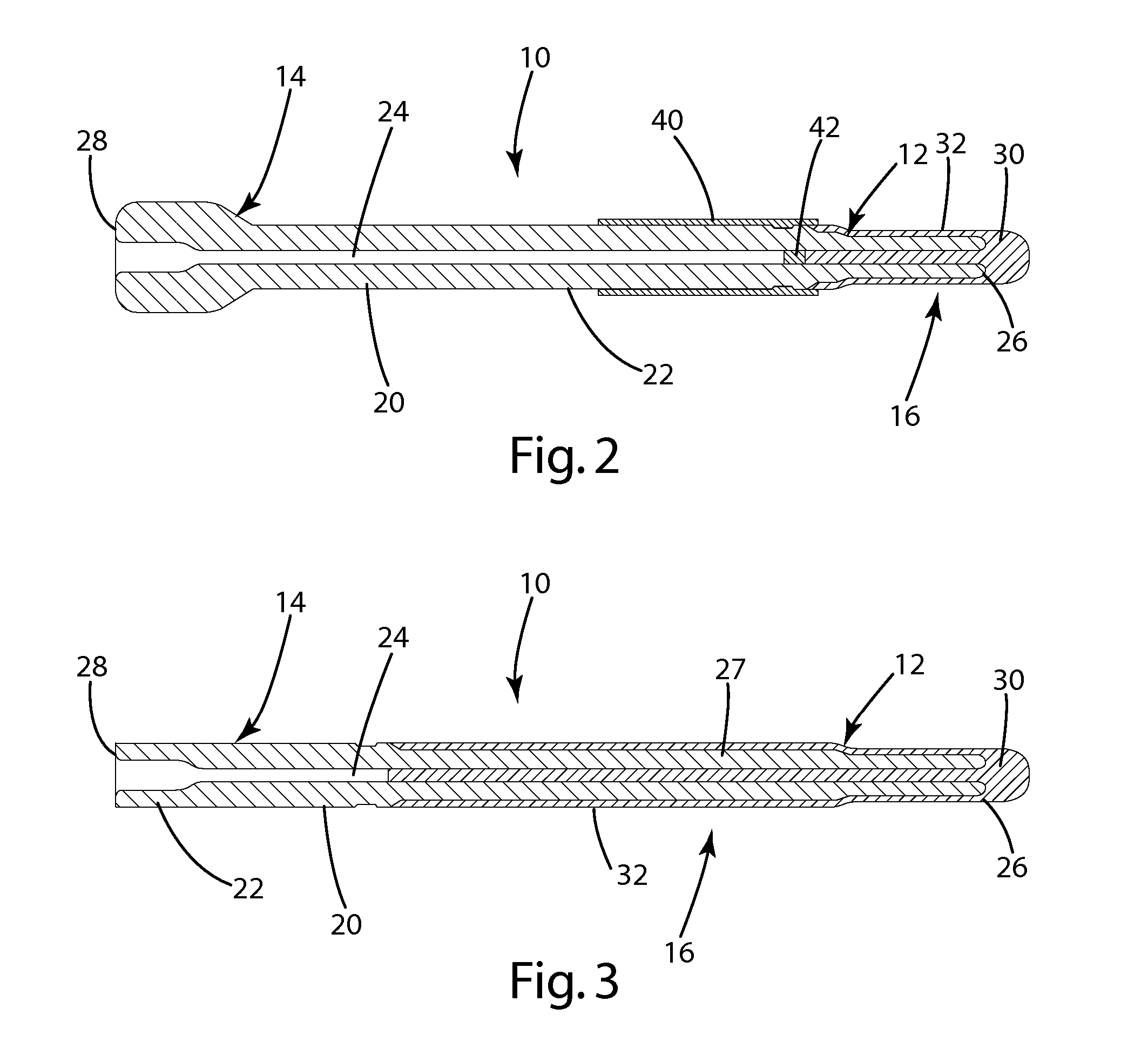
[0024] The present invention, as illustrated in FIGS. 2-5, is directed to a heating element 10 having an electrically insulative layer 20, formed from an electrically insulative material, and an electrically conductive layer 30, formed from an electrically conductive material. As illustrated in FIG. 2, the conductive material is attached to a first electrical contact 40 and a second electrical contact 42 which allow electrical current to flow through the conductive material to generate heat that is primarily focused where the thickness of the conductive layer 30 is at its thinnest point and has the smallest cross cross-sectional area. Although only FIG. 2 is illustrated with the electrical contacts, 40 and 42, the heating element 10 will be generally formed with electrical contacts, which may vary in size, shape and configuration. The heating element also may include a base portion 14 formed in a variety of configurations and shapes.

[0025] The insulative layer 20 further includes a...


PUM


Abstract

A heating element and, in particular, a ceramic heating element, such as ceramic heating elements used in high temperature glow plugs for diesel engines and gas igniters. The heating element includes an electrical insulator and an electrically conductive layer. The conductive layer is formed from a single material and single composition. The method of manufacture includes the steps of forming the insulative layer and molding a conductive layer around the insulative layer.

Description

CROSS-REFERENCE TO RELATED APPLICATIONS [0001] This application claims priority to U.S. Provisional Application Ser. No. 60 / 785,334, filed Mar. 23, 2006 which is incorporated herein by reference.BACKGROUND OF THE INVENTION [0002] The present invention relates to a heating element and, in particular, a ceramic heating element, such as ceramic heating elements used in high temperature glow plugs for diesel engines and gas igniters, and methods of manufacture therefore. [0003] Ceramic heating elements, such as the glow plug illustrated in FIG. 1, are well known in the industry. As illustrated in FIG. 1, a glow plug 2 typically includes a heating element having an electrically conducting core 8 surrounded by an electrically insulative layer 6. The insulative layer 6 is in turn surrounded by an outer resistive layer 4 which makes contact with the conducting core 8 at the electrical connection area 9. To manufacture the glow plug 2, illustrated in FIG. 1, the layered structure is formed b...

Claims


Application Information

Patent Timeline
IPC IPC(8): F23Q7/22
CPCF23Q7/001F23Q2007/004H05B2203/027H05B3/42H05B3/141
Inventor WALKER, WILLIAM J. JR.HOFFMAN, JOHN W.MAY, JAMES L.
Owner FEDERAL MOGUL WORLD WIDE
Learn More