
Training apparatus

a training apparatus and training technology, applied in the field of training machines, can solve the problems of inability to exercise appropriately, insufficient increase the effectiveness of exercise, inappropriate load change for trainees, etc., and achieve the effect of increasing the load in the forward path, effective variation of load, and improving exercise effectiveness

Inactive Publication Date: 2007-09-20
KONAMI SPORTS & LIFE
View PDF13 Cites 23 Cited by
  • Summary
  • Abstract
  • Description
  • Claims
  • Application Information

AI Technical Summary

Benefits of technology

[0011]To take the trainee's physique into account in the range of motion, a load that is suited to the trainee's physique is applied by varying the load in accordance with the position in the range of motion, and thereby the trainee can be made to exercise effectively. The range of motion is preferably determined by measurement. This is because the range of motion that is obtained by measurement can take into account the trainee's physique, joints, etc. The range of motion of each individual trainee is measured at least once, and is preferably measured continuously or intermittently. For example, it may be measured at prescribed time intervals, or prior to or at the start of every exercise. If the range of motion is measured prior to or at the start of every exercise, then it is possible to apply a load in accordance with the trainee's condition, which changes daily, and therefore the trainee improves his or her form when performing exercises.
[0012]The method of varying the load is not particularly limited. For example, a reference load is applied at the start point of the forward path in an abdominal muscles exercise, wherein the trainee leans his or her upper body forward, and a terminal load (terminal load>reference load) is applied at the end point of the forward path. When performing a forward bend exercise, it becomes easier for the trainee to exert his or her abdominal muscles at the end point of the forward path and, consequently, the training becomes commensurately easier; therefore, the load is conversely increased just to the extent that the training has become easier, and it is therefore possible to maintain substantially the same training effect throughout the entire repetitive exercise and thereby make the trainee train effectively. In addition, for example, the load is increased in the vicinity of the center of the forward path in a barbell exercise. The reference load is applied at the start point and the end point of the forward path, and the reference load×N (1<N<2) is applied in the vicinity of the center of the forward path. Applying a heavy load at the sticking point in a barbell exercise makes it possible to effectively stimulate the target muscle.
[0024]The method of varying the load can be changed in accordance with the exercise type. Thereby, it is possible to effectively vary the load for each type of exercise and to improve the effectiveness of the exercise. For example, if the exercise is the abovementioned abdominal muscles exercise, then the load in the forward path is increased linearly, and the load in the return path is decreased linearly. If the exercise is the barbell exercise, then the load in the forward path is first increased linearly and then decreased linearly, and the load is maintained at a fixed value in the return path.
[0025]According to the present invention, the exercise effect of each individual trainee can be enhanced because the load can be varied in accordance with the trainee's physical build.

Problems solved by technology

However, if the load is applied uniformly to every trainee in accordance with the torque and the rotational speed of the direct drive motor, then the control of the load will be perfect for trainees who have a standard physique, but the change in the load will be inappropriate for trainees who have a build that is smaller or larger than the standard physique.
Consequently, the latter trainees cannot exercise appropriately and, therefore, cannot, for example, sufficiently increase the effectiveness of the exercise or are forced into overexertion.

Method used


Image

  • Training apparatus
  • Training apparatus
  • Training apparatus

Examples


first embodiment

Training Apparatus Configuration

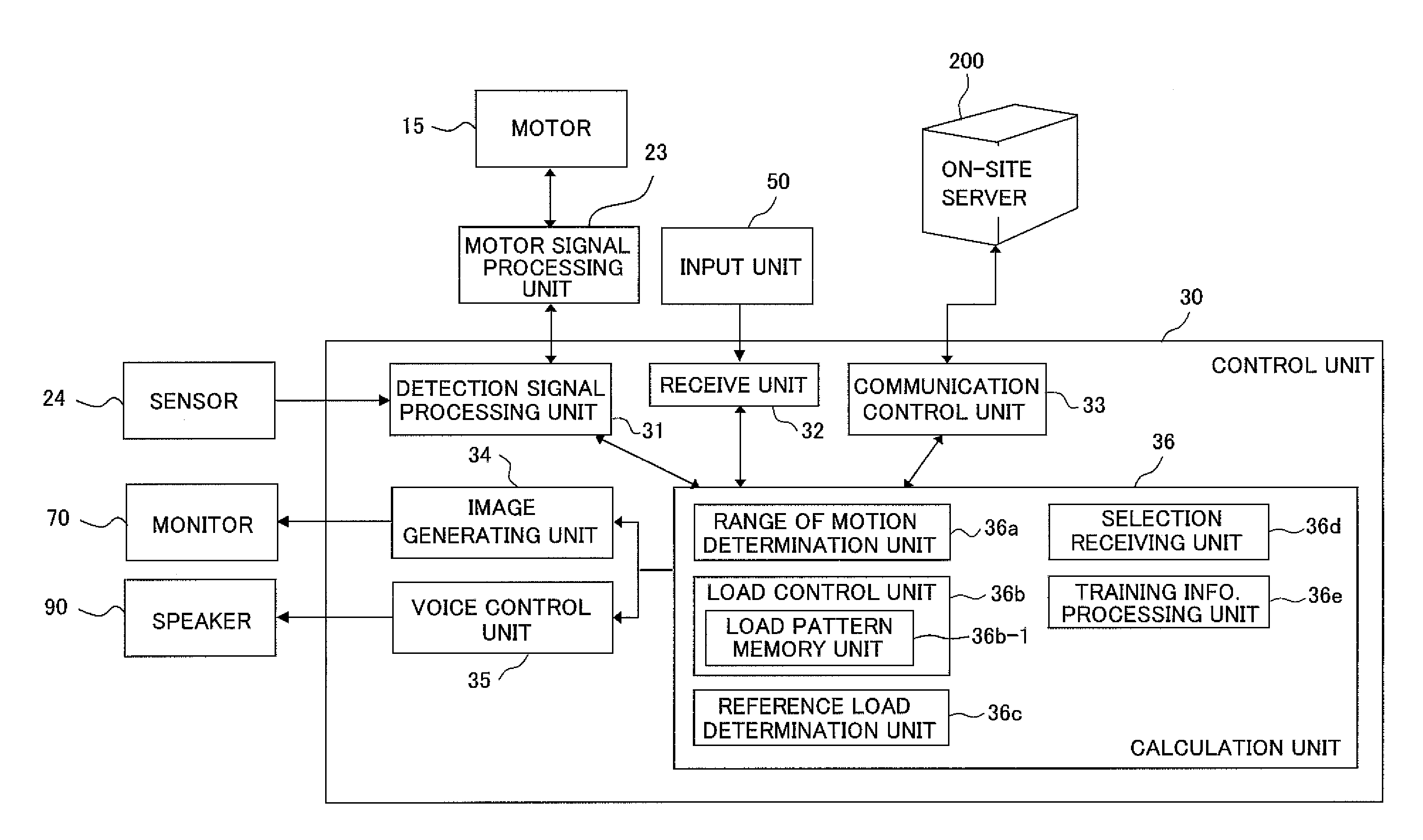
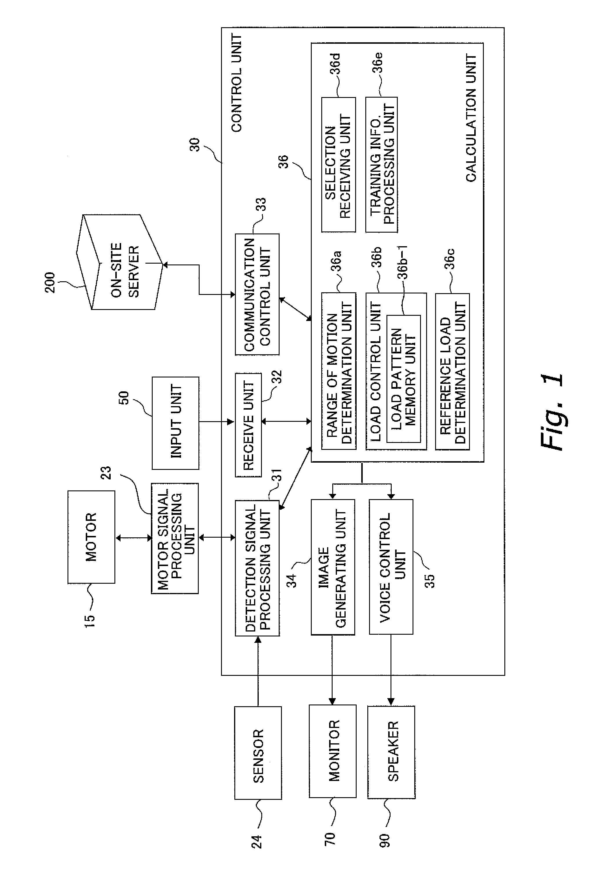
[0049]FIG. 1 is an explanatory diagram that shows the hardware configuration and the functional configuration of a training apparatus 100 according to the first embodiment of the present invention. The hardware configuration and the functional configuration of the training apparatus 100 will now be explained successively, referencing FIG. 1.

(1) Hardware Configuration

(1-1) Overall Configuration

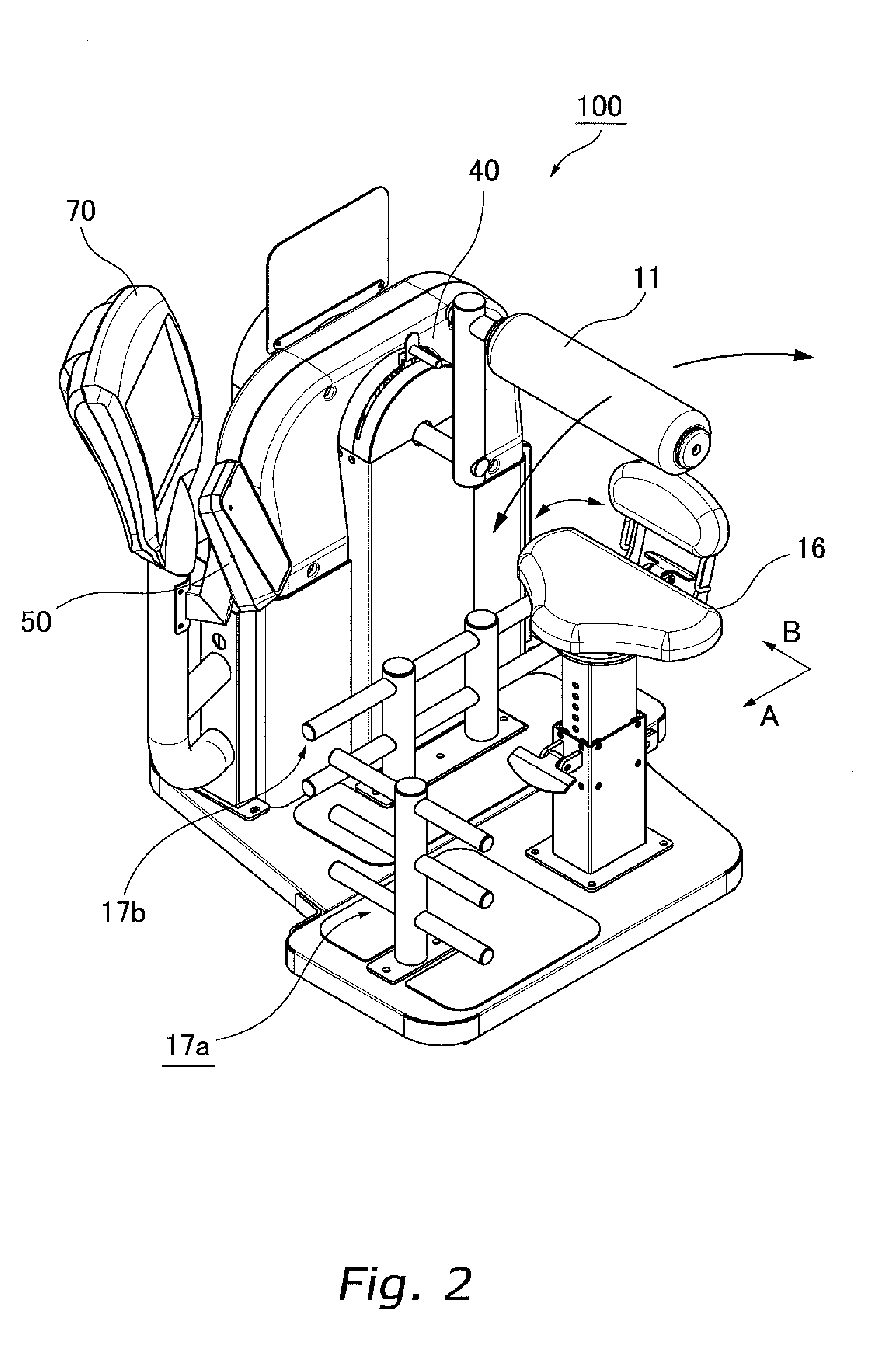
[0050]The training apparatus 100 is installed in, for example, a facility such as a health club, and is connected to an on-site server 200. The server 200 accumulates personal data of trainees and transmits such in response to requests from the training apparatus 100. Furthermore, in the present embodiment, the server 200 is only installed in a facility such as a health club, but an off-site server (not shown) can also be provided that connects on-site servers nationally or globally. Membership data may be accumulated in such an off-site server and each on-site s...


PUM


Abstract

A training apparatus is disclosed that will enable a trainee to exercise with a load that is suited to his or her physical build in the forward path and return path of a repetitive exercise. A motor applies a load to a bar (corresponds to a moving unit) that moves repetitively due to a trainee's exercise. The load that is applied by the motor is not fixed, but rather varies during the repetitive exercise. The width of the repetitive exercise, i.e., the width of the range of motion of the bar, takes into account differences in the physique of individual trainees. Consequently, varying the method by which the load changes in accordance with the width of the range of motion makes it possible to apply a load that is suited to the physique of each individual trainee, thereby enabling each trainee to exercise effectively.

Description

CROSS-REFERENCE TO RELATED APPLICATIONS[0001]This application claims priority to Japanese Patent Application No. 2006-061528. The entire disclosure of Japanese Patent Application No. 2006-061528 is hereby incorporated herein by reference.BACKGROUND OF THE INVENTION[0002]1. Field of the Invention[0003]The present invention relates to a training machine that is used by an individual to exercise in order to improve physical strength.[0004]2. Background Information[0005]A variety of training machines have been proposed in the past that enable an individual to exercise with an appropriate load. Among these various training machines, there are machines with which a trainee performs repetitive exercise while a load is applied to certain muscles in order to work the muscles that he or she has targeted. For example, Japanese Examined Utility Model Application No. S7-41083 proposes an apparatus for the purpose of training by performing repetitive exercise. This training apparatus uses a direc...

Claims


Application Information

Patent Timeline
Patent Type & Authority Applications(United States)
IPC IPC(8): A63B15/02A63B21/00
CPCA63B21/0058A63B23/0211A63B23/0227A63B23/0233A63B21/1492A63B24/0062A63B2024/0065A63B2208/0233A63B2220/16A63B23/0244A63B21/4047
Inventor HAYASHINO, TAKEAKIMATSUBARA, MAYUTSUJI, TAKESHIYONAI, YUKIHARADA, AMIKA
Owner KONAMI SPORTS & LIFE
Learn More