
Aperture construction for a mobile camera

a mobile camera and aperture technology, applied in the field of digital cameras, can solve the problems of reducing the usability range, affecting the operation of the camera, so as to reduce the complexity and size of the prior art aperture, simplify the manufacturing process, and reduce the risk of breaking or jamming

Active Publication Date: 2007-09-20
NOKIA TECHNOLOGLES OY
View PDF5 Cites 17 Cited by
  • Summary
  • Abstract
  • Description
  • Claims
  • Application Information

AI Technical Summary

Benefits of technology

[0010] The object of the invention is to overcome the problems related to the prior art aperture implementations above. Especially the object of the invention is to reduce the complexity and size of the prior art aperture, simplify the manufacturing process, and provide a fully adjustable stepless aperture with a circular shape and with minimal power consumption.
[0016] The embodiments of the present invention change the prior art mechanical structure implemented with several moving parts, which have been used to construct an adjustable hole traditionally, to one piece element with no moving parts and built-in sensing capability. Therefore the system complexity will reduce significantly and the size becomes smaller.
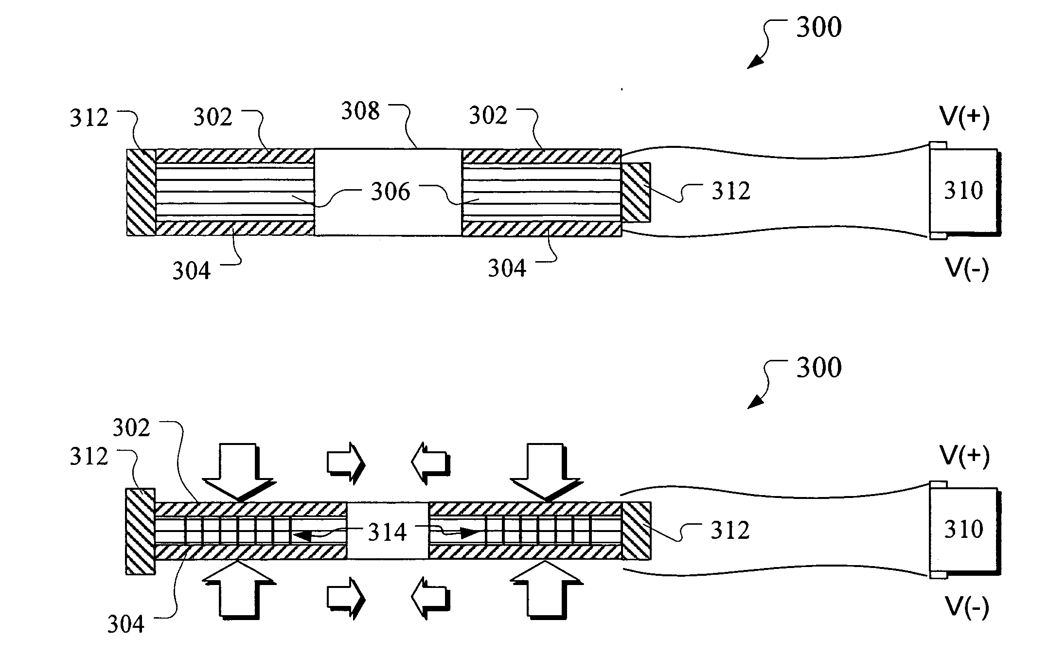
[0017] One important part of the aperture (construction?) of the present invention is a center unit. The center unit, with no separated moving parts, is capable of expanding and retracting the aperture in the middle. One advantageous idea of the invention is based on to the utilization of an electroactive material, such as a dielectric material or electrostrictive polymer, which is placed between electrodes. Applied voltage will create an electrical field between the electrodes, which will then deform, “squeeze”, the electroactive material, causing it to expand and / or retract. The aperture size is controlled with operating voltage by an operating circuit and measured by the capacitance or resistance of the circuit. Thus a very simple application is enabled with built-in sensing capability.
[0018] Embodiments of the invention offer clear advantages over the known prior art. The system complexity can be reduced to one element instead of 10-20 pcs of small parts. Moreover the current aperture size can be sensed easily and accurately by electrically from capacitance or resistance value of the circuit controlling the center unit. The weight and size of the aperture unit is much smaller than in conventional apertures. In addition the aperture of the invention only consumes power when the aperture size is changed. In a static state (fixed aperture size is maintained) no current goes through the system. Furthermore fully adjustable (stepless) aperture without moving parts and fully circular aperture shapes can be created. Still the aperture of the invention can be used as a diaphragm shutter (combination of shutter and aperture) because of rapid response times (mSec levels) because of the electroactive material used in the center unit of the aperture.

Problems solved by technology

These solutions are typically compromises between overall size and achieved image quality, or lead to decrease in range of usability.
However, some problems relate to the prior art aperture implementations.
At first they are very complex whereupon there is a risk to break down or jam.
Secondly the shape of the prior art aperture is not fully circular, which can affect distortions into the picture.
In addition weight and size of the prior art aperture are not easily reduced by conventional manners.
Furthermore the manufacturing of the prior art aperture implementation is quite complex and time consuming because of the complexity of the aperture structure.

Method used


Image

  • Aperture construction for a mobile camera
  • Aperture construction for a mobile camera
  • Aperture construction for a mobile camera

Examples


Embodiment Construction

[0027] FIGS. 1A-B illustrating effects of different aperture sizes (f-number) to the depth-of-field in two exemplary pictures, as well as FIG. 2 illustrating an exemplary exploded view of an implementation for adjustable aperture construction known from the prior art, and FIGS. 2A-D illustrating different aperture sizes achieved by a wing mechanism with the actuator known from the prior art, have already discussed in the connection with the prior art description (background of the invention chapter).

[0028]FIG. 3A illustrates a section view of an aperture construction 300 according to an advantageous embodiment of the present invention, where the aperture construction comprises a positive electrode 302 and negative electrode 304. Between the positive and negative electrodes is placed a center unit 306 with a hole 308 in the middle. The center unit is made of an electroactive material. Moreover the aperture construction comprises also an electrical circuit 310 for applying a voltage ...


PUM


Abstract

The invention relates in general to the field of digital cameras, especially small digital cameras. In particularly the invention relates for adjusting an aperture for mobile cameras. The adjustable aperture construction of the invention comprises two electrodes, and an electrical circuit for applying a voltage to the electrodes in order to create an electric field between the electrodes. In addition the construction comprises between the electrodes a center unit with a hole in the middle of it, the center unit being made of an electroactive material, such as dielectric material or electrostrictive polymer. The aperture can be adjusted by deforming the shape of the center unit. The shape of the center unit is advantageously deformed by the electric field created between said electrodes by said electrical circuit.

Description

TECHNICAL FIELD OF THE INVENTION [0001] The invention relates in general to the field of digital cameras, especially small digital cameras. In particularly the invention relates for adjusting an aperture for mobile cameras. BACKGROUND OF THE INVENTION [0002] Nowadays mobile cameras, such as digital cameras and mobile phone cameras are very common. The size of the mobile camera has an essential role, when the mobile camera is integrated with other mobile device, such as a mobile phone, watch, MP3-player or pocket computer. The size of the camera can be reduced by reducing the size of the camera's components, such as lens, shutter, aperture construction (sometimes combination of shutter and aperture, namely diaphragm shutter) and image sensors. The smaller the camera's component, the smaller the camera is and also smaller the end product. Also the simplicity, reliability and power consumption of the camera's components are very important factors in mobile camera devices. [0003] It is ...

Claims


Application Information

Patent Timeline
Patent Type & Authority Applications(United States)
IPC IPC(8): H04N7/00G03B9/00G03B7/085G03B9/02G03B9/06G03B17/02H04N23/75
CPCG02B5/005G02B13/0075G03B9/02G03B7/085G02B26/02H01M4/02
Inventor EROMAKI, MARKO
Owner NOKIA TECHNOLOGLES OY
Learn More