
Nagata cycle rotary engine

a rotary engine and cycle technology, applied in the direction of liquid fuel engines, machines/engines, rotary piston liquid engines, etc., can solve the problems of rotary engines that have not enjoyed wide-spread production or success, rotary engines have been plagued by several problems, and significant ones still exist, so as to achieve superior gas mileage and performance.

Inactive Publication Date: 2007-09-20
NAGATA SUMIYUKI +1
View PDF18 Cites 10 Cited by
  • Summary
  • Abstract
  • Description
  • Claims
  • Application Information

AI Technical Summary

Benefits of technology

[0009] Further objectives and advantages are to provide an engine that, because of the ab

Problems solved by technology

Since its invention in the 1950's the rotary engine has not enjoyed wide-spread production or success.
Although several of the problems with the rotary engine have been corrected, significant ones still exist.
Historically, rotary engines have been plagued by several problems.
Leakage under pressure has been an issue with designs since Ramelli first invented the rotary pump in 1588.
Later internal combustion designs all had overheating as a common design fault.
Additionally, rotary engines have had gas mileage far below the industry standard and are notorious for needing major engine seal repairs.
(a) Friction—because of their high rotational speed rotary engine designs create considerable centrifugal force resulting in friction.
(b) Sealing—chamber leakage under pressure wastes fuel and reduces engine efficiency.
Another problem specific to the technology presented herein is with vanes which serve to create separate chambers within an engine.
Vanes are a common component in pumps and compressors but have not found success in combustion engines due to durability and sealing issues.

Method used


Image

  • Nagata cycle rotary engine
  • Nagata cycle rotary engine
  • Nagata cycle rotary engine

Examples


Embodiment Construction

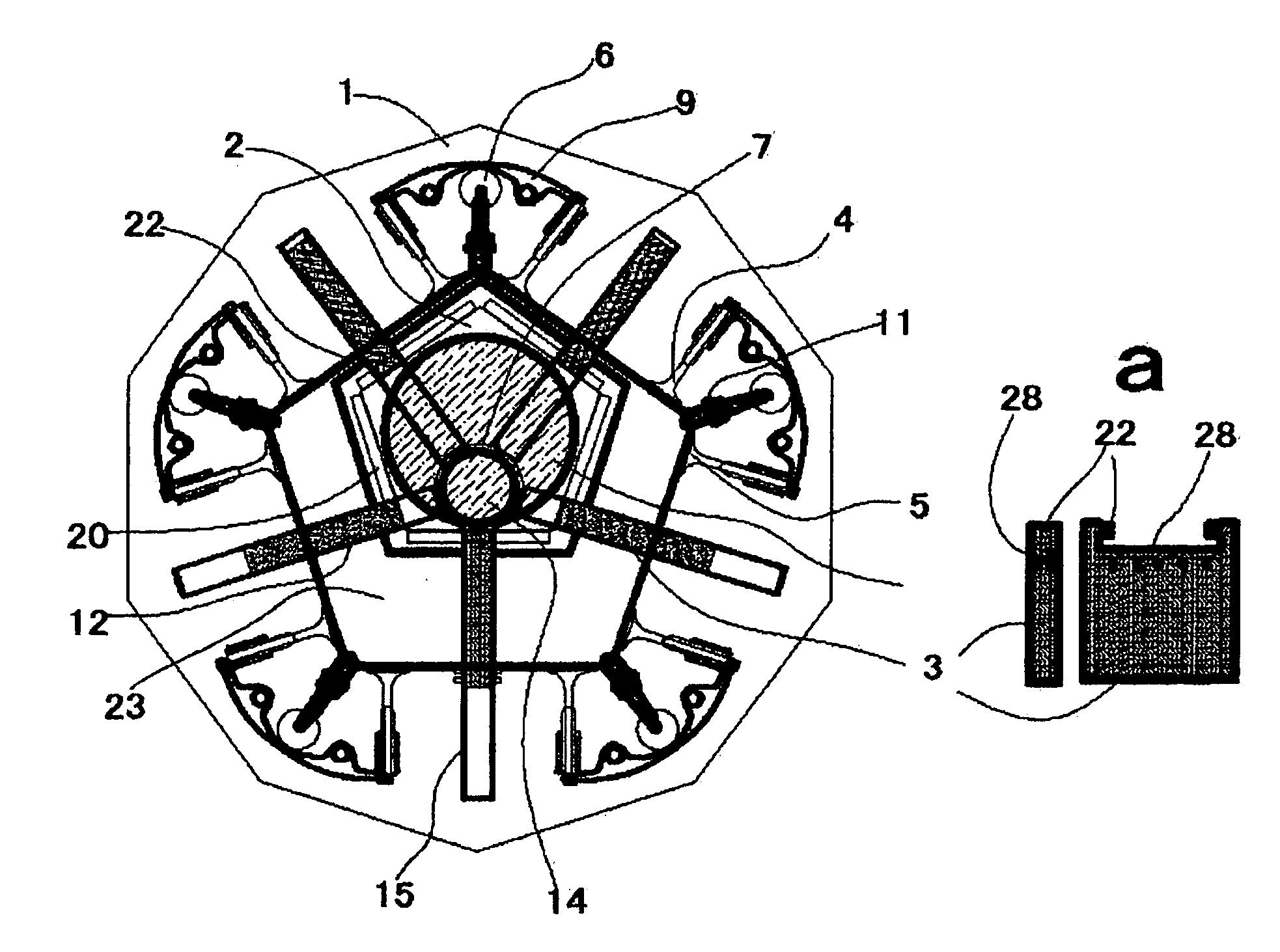
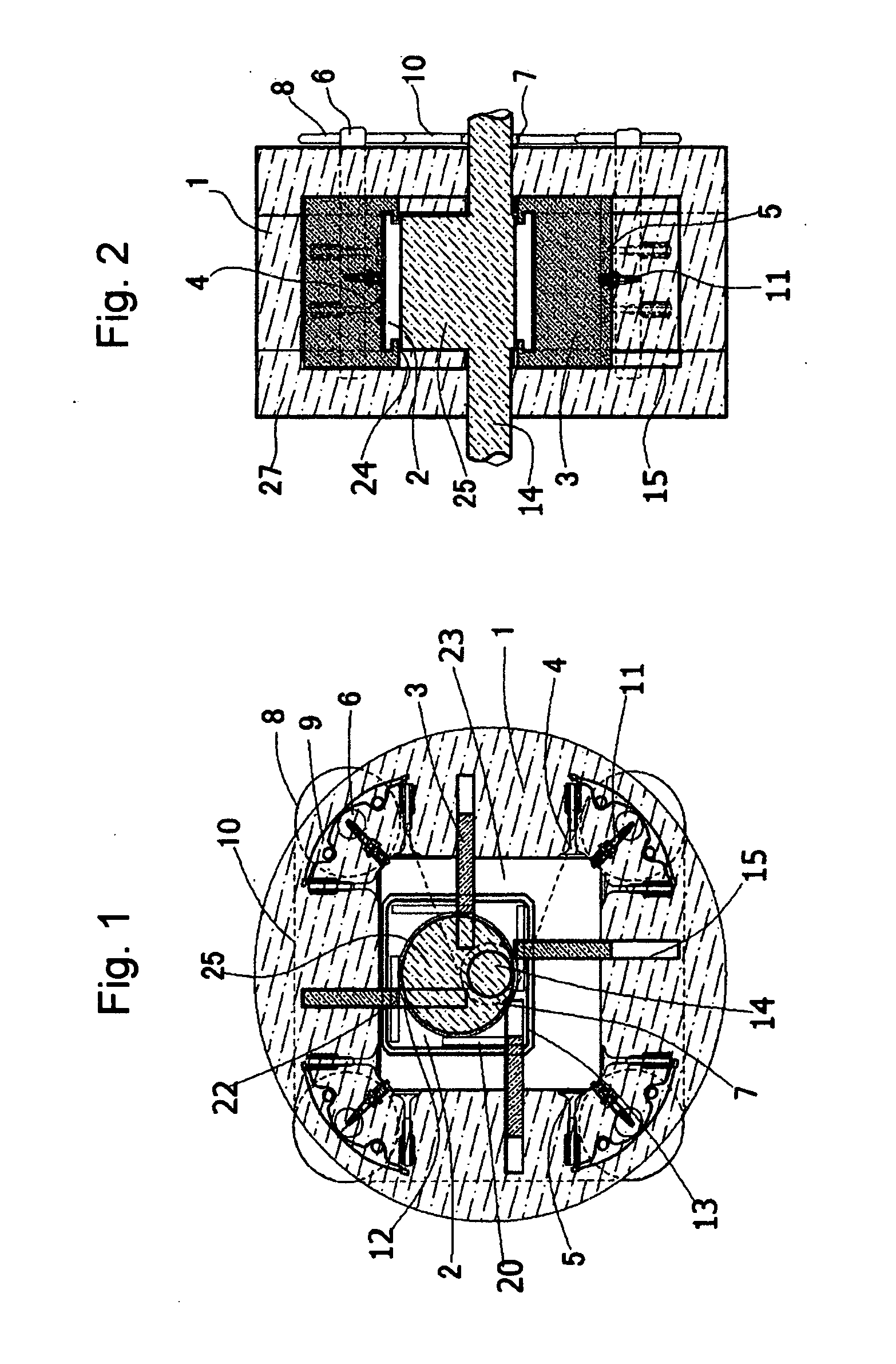
[0021] An embodiment of the present invention is illustrated in FIG. 1. Additionally, FIGS. 4 and 5 depict possible embodiments with different shapes and numbers of working engine chambers.

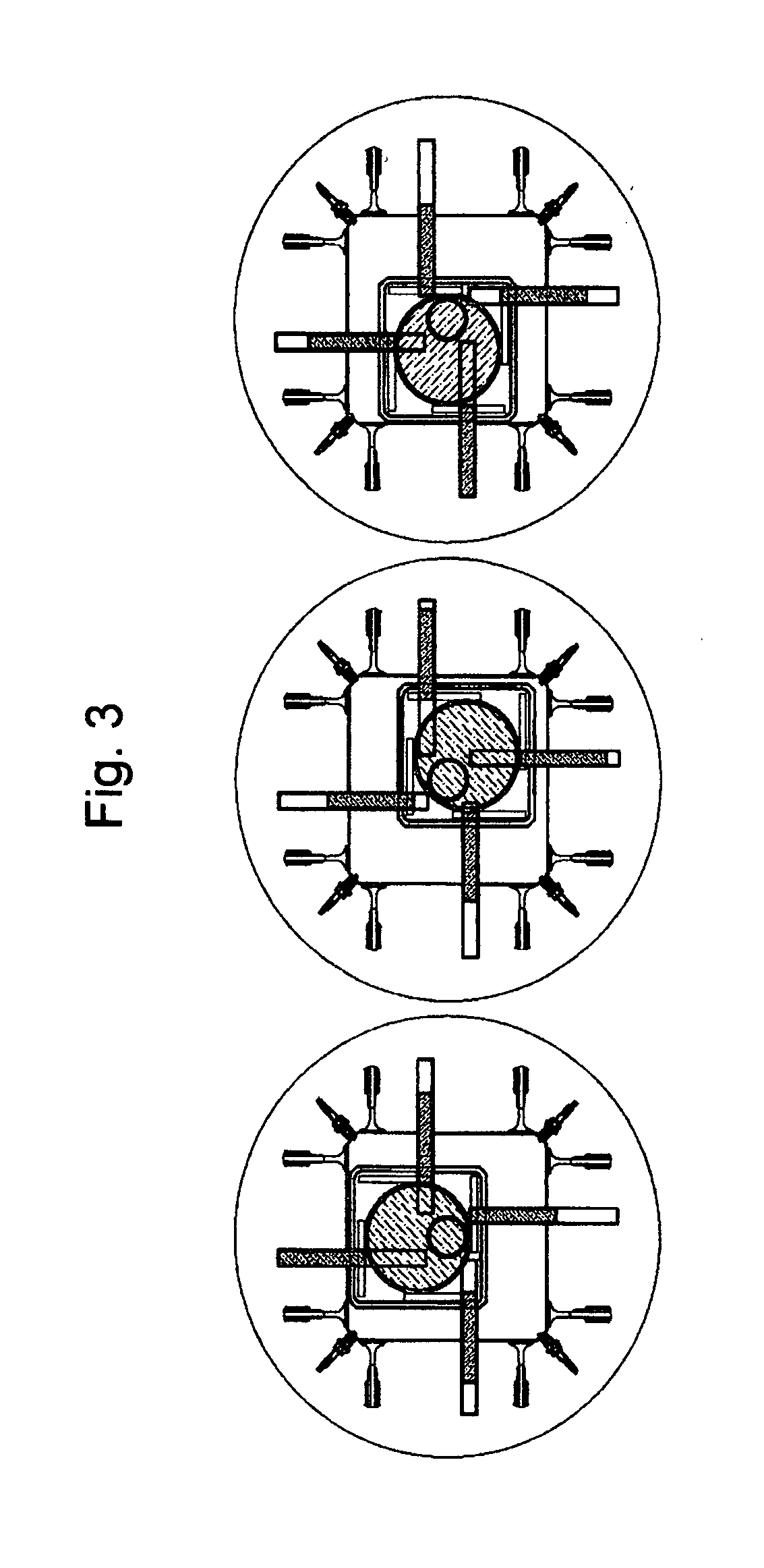
[0022] The engine has housing (1), which in this case has an inner wall which is a four sided polygon. Rotor (2), which in this case is also a four sided polygon, is contained inside housing (1) and is positioned off-center of drive shaft (14), allowing it to displace the fuel / air mixture about the engine chamber.

[0023] Vanes (3) extending between rotor (2) and the inner wall of housing (1) create separate chamber rooms (23) within the engine and are supported on each end by either rotor-side vane pins (22) or the vane recess (15) they slide in and out of in the side housing. Vane motion is restricted to rolling freely along vane channels (12) located in the inner wall of each end housing. Vane pin slots (20) located around the periphery of rotor (2) allow the rotor to be in slideable contact wi...


PUM


Abstract

An internal combustion rotary engine using vanes to create separate combustion chambers within the engine and capable of performing all four strokes of the Otto cycle (intake, compression, combustion and exhaust) in each separate combustion chamber. Each Otto cycle is completed in a 180-degree rotation with all four strokes of the Otto cycle being completed in 720 degrees. An intake and exhaust valve system tightly controls the flow of the air / fuel mixture into each separate combustion chamber.

Description

[0001] Reference Japan Patent Application No. 2006-102445 filed Mar. 6, 2006 [0002] Small entity status claimed under 35 USC 41 FIELD OF THE INVENTION [0003] This invention relates to rotary internal combustion engines, pumps and compressors. DESCRIPTION OF THE PRIOR ART [0004] Since its invention in the 1950's the rotary engine has not enjoyed wide-spread production or success. The first mass produced rotary engine was the Wankel Rotary Engine (1950). It was invented as an alternative to the piston engine. The main advantage of the rotary engine is its compact and efficient layout. [0005] Since the invention of the original rotary engine several of the problems plaguing the design have been corrected. One such improvement is the apex seal which serves to reduce friction and fuel loss. Although several of the problems with the rotary engine have been corrected, significant ones still exist. [0006] Historically, rotary engines have been plagued by several problems. Leakage under pres...

Claims


Application Information

Patent Timeline
IPC IPC(8): F02B53/00
CPCF01C1/32
Inventor NAGATA, SUMIYUKICOBB, RYAN WILLIAM
Owner NAGATA SUMIYUKI
Learn More