High rate charging and discharging cylindrical secondary battery
- Summary
- Abstract
- Description
- Claims
- Application Information
AI Technical Summary
Benefits of technology
Problems solved by technology
Method used
Image
Examples
example 1
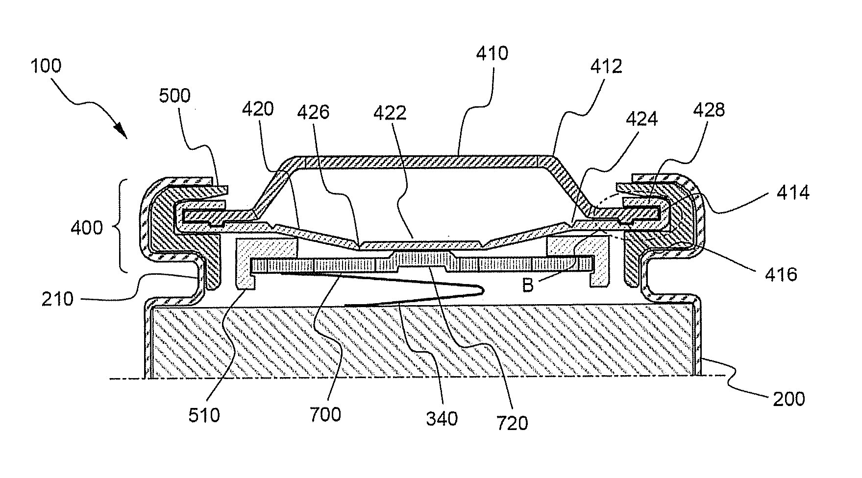
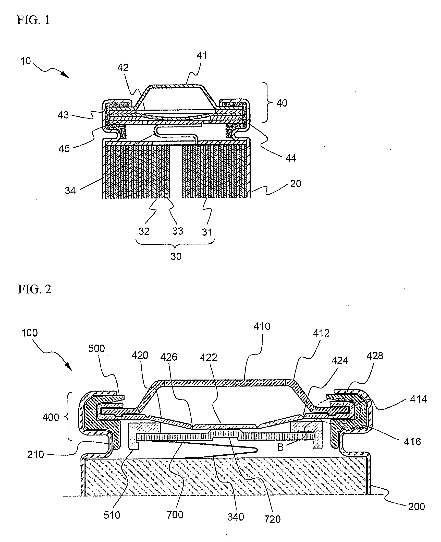
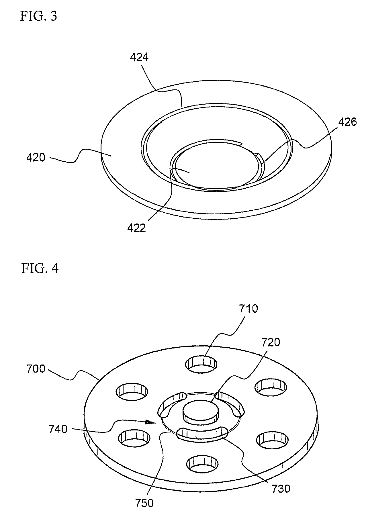
[0061] A top cap was manufactured using a cold rolled carbon steel sheet (SPCE) coated with Ni, and a vent having the structure shown in FIG. 3 and a current intercepting member having the structure shown in FIG. 4 were manufactured using an aluminum sheet (Al1050-H24). At the lower end surface of the top cap was continuously formed a groove having a width of 0.6 mm and a height of 0.04 mm in a concentric shape.
[0062] The vent was formed in the shape of a plate member having an outer diameter of 16 mm and a thickness of 0.3 mm. A first notch constituting the upper bent region of the vent was formed with a diameter of 10 mm and a thickness of 0.13 mm, and a second notch constituting the lower bent region of the vent was formed with a diameter of 4 mm and a thickness of 0.09 mm. The current intercepting member was formed in the shape of a plate member having an outer diameter of 11 mm and a thickness of 0.5 mm. Six gas discharging holes having a diameter of 3 mm were radially formed ...
experimental example 1
[0066] While 10 batteries manufactured as described in Example 1 and 10 batteries manufactured as described in Comparative example 1 were placed upside down, a pressure was applied into the cells to 15 Kgf so as to check whether an electrolyte leaked from the corresponding battery before the current intercepting member was broken. The results are indicated in Table 1.
TABLE 1Occurrence ofOccurrence ofleakageOccurrence ofleakage beforesimultaneouslyleakage afterbreakage ofwith breakagebreakage ofcurrentof currentcurrentNonoc-interceptinginterceptinginterceptingcurrencemembermembermemberof leakageExample 10 / 100 / 100 / 1010 / 10Compar-4 / 101 / 102 / 10 3 / 10ativeexample 1
[0067] It can be seen from Table 1 that the electrolyte did not leak from the batteries of Example 1, whereas the electrolyte leaked from the batteries of Comparative example 1 before and after the breakage of the current intercepting member.
experimental example 2
[0068] While 12 batteries manufactured as described in Example 1 were fully charged to 4 A and 4.2 V. The fully charged batteries were put into an octagonal drum, and the batteries were revolved at a speed of 66 rpm for 30 minutes. After that, the impedance of the respective batteries was measured. Under the same conditions, the 12 batteries were revolved for 150 minutes, and then the impedance of the respective batteries was measured. It can be interpreted that, when the increase rate of the impedance after the drum test to the impedance before the drum test is less than 10%, the electrical connection of the batteries is excellent. The experimental results are shown in FIG. 10.
[0069] In addition, 12 batteries manufactured as described in Comparative example 1 were repeatedly tested in the same manner. The experimental results are shown in FIG. 11.
[0070] As can be seen from these drawings, the increase of the impedance of the batteries of Example 1 was very small after the 30-minu...
PUM
 Abstract
Description
Claims
Application Information
 - R&D
- Intellectual Property
- Life Sciences
- Materials
- Tech Scout
- Unparalleled Data Quality
- Higher Quality Content
- 60% Fewer Hallucinations
Browse by: Latest US Patents, China's latest patents, Technical Efficacy Thesaurus, Application Domain, Technology Topic, Popular Technical Reports.
© 2025 PatSnap. All rights reserved.Legal|Privacy policy|Modern Slavery Act Transparency Statement|Sitemap|About US| Contact US: help@patsnap.com


