Apparatus, System And Method For Optical Signal Transmission

a technology of optical signal and apparatus, applied in the field of broadband signal transmission, can solve the problems of poor receiving sensitivity, increased overall cost, and inability to use commercially available bs/cs tuners, so as to facilitate frequency separation of two transmitted signals, reduce and avoid spurious interference, and be inexpensive.

Inactive Publication Date: 2007-09-13
NIPPON TELEGRAPH & TELEPHONE CORP
View PDF3 Cites 15 Cited by
  • Summary
  • Abstract
  • Description
  • Claims
  • Application Information

AI Technical Summary

Benefits of technology

[0029] As described above, the present invention makes it possible to frequency-multiplex two signals, at least one of which being FM batch converted, and to transmit the signals as an optical signal over a single optical fiber line simultaneously.
[0030] On the receiving end, the present invention makes it possible to convert the transmitted optical signal to an electrical signal by a single photo-receiving element and to frequency-separate the two signals.
[0031] Furthermore, with an appropriate frequency allocation of the FM batch converted signal and the other signal, frequency-separation of the two transmitted signals can be facilitated, enabling to reduce and avoid spurious interference. As a result, an optical signal transmission system can be realized with an inexpensive configuration.
[0033] As for the transmitted RF signal of the BS / CS satellite broadcasting, the BS / CS down-converter circuit built-in a commercially available BS / CS antenna can be used without modification. Furthermore, since the signal is converted to an IF signal by the down-converter circuit, compatibility with a commercially available BS / CS tuner can be maintained. Thereby, video receiving equipment on the subscriber side can be configured inexpensively.

Problems solved by technology

However, a problem exists in that if the BS / CS signal is to be compressed and frequency-converted to the CATV signal frequency band of 90 to 770 MHz, a commercially available BS / CS tuner may not be used.
However, such transmission scheme using intensity modulation has an inherent problem of a poor receiving sensitivity.
However, a problem arises when multiplexing the CATV signals and the BS / CS signals in frequency by this FM batch conversion scheme based on the ITU standard.
However, in this method, since two photo-receiving elements such as photo diodes (PDs) or avalanche diodes (APDs), are required for each receiver, this results in an increased number of circuit components as well as in an increased overall cost. FIG. 1 shows an exemplary configuration of this method.
In this case, for the operating frequency of an FM demodulator for demodulating the FM batch converted signal, a high speed operation of 8 GHz or higher is required, leading to a problem that a conventional FM demodulator with a frequency of about 6 GHz cannot be used.

Method used


Image

  • Apparatus, System And Method For Optical Signal Transmission
  • Apparatus, System And Method For Optical Signal Transmission
  • Apparatus, System And Method For Optical Signal Transmission

Examples


embodiment 1

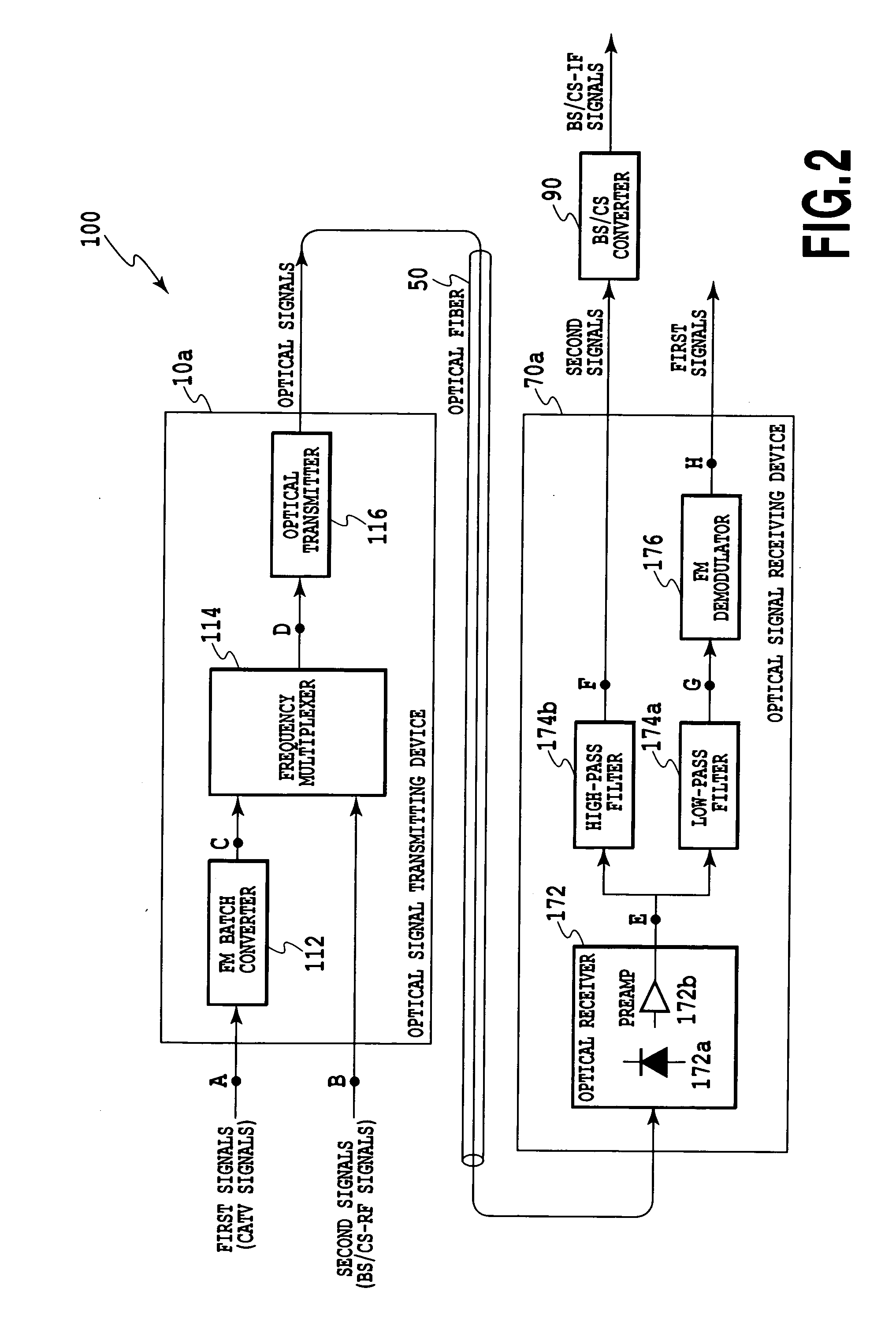
[0055] As shown in FIG. 2, the optical signal transmitting device 10a comprises an FM batch converter 112 for FM converting a first signal in batch, a frequency multiplexer 114 for multiplexing the FM batch converted signal and a second signal in frequency, and an optical transmitter 116 for modulating an optical signal in intensity with the frequency-multiplexed electrical signal.

[0056] In the figure, the first signal such as CATV broadcasting signal (90 to 770 MHz) is provided (at point A) and the second signal such as BS / CS satellite broadcasting RF signal (11.7 to 12.8 GHz) is provided (at point B). In general, the CATV signal is a signal with multi-channel video signals being multiplexed via frequency-division whereas the RF signal of the BS / CS satellite broadcasting is also a signal with multi-channel video signals being multiplexed via frequency-division. The BS / CS satellite broadcasting RF signal may be a signal which is up-converted from an IF frequency band (1030 to 2070 ...

embodiment 2

[0067]FIG. 5 shows a configuration of an optical signal transmitting device 10b according to an embodiment of the present invention. The optical signal transmitting device in FIG. 5 comprises a batch FM converter 212 for FM converting the first signal in batch, a first optical transmitter 214a for modulating an optical signal in intensity with the FM batch converted signal, a second optical transmitter 214b for modulating an optical signal in intensity with a second signal, and an optical multiplexer 216 for multiplexing the intensity-modulated first and second optical signals.

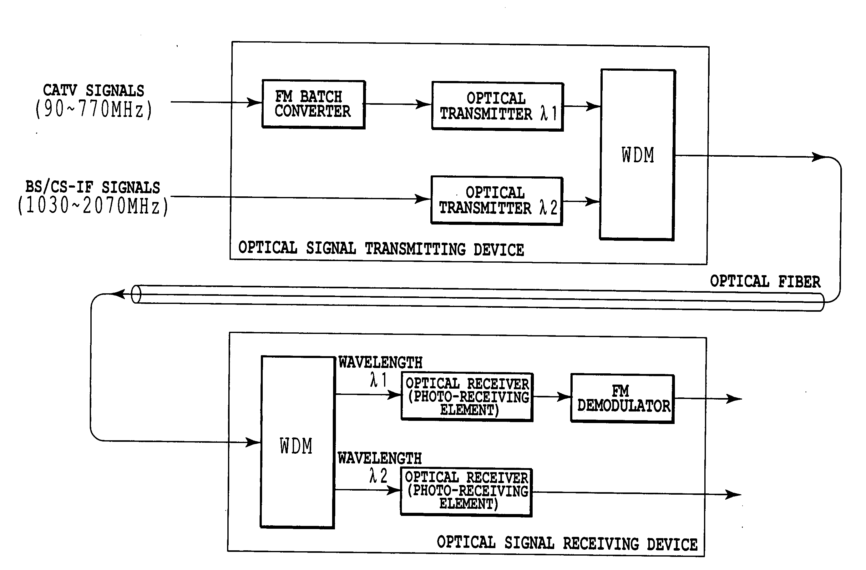
[0068] In this embodiment 2, the wavelength of the first optical transmitter and the wavelength of the second optical transmitter are required to be separated to an extent that no interference noise does occur. For example, if the optical wavelength of the first optical transmitter and the optical wavelength of the second optical transmitter are separated by 13 GHz or more, the differential component between ...

embodiment 3

[0070]FIG. 6 shows a configuration of an optical signal transmitting device 10c according to an embodiment of the present invention. The optical signal transmitting device 10c in FIG. 6 comprises a batch FM converter 312 for FM converting a first signal in batch, an optical transmitter 314 for modulating an optical signal in intensity with the FM batch converted signal, and an external modulator 316 for modulating the FM batch converted and intensity-modulated optical signal with a second signal. For the external modulator such as a Mach-Zehnder type based on LiNbO3, or an electro-absorption modulator can be used.

[0071]FIG. 7 shows frequency spectra when the optical signal at point D in FIG. 6 is photoelectrically converted to electrical spectra. From the figure, it can be seen that an FM batch converted spectra and the second signal spectra are frequency-multiplexed in effect.

[0072] When modulating by an external modulator, which generally means performing multiplication, frequen...


PUM


Abstract

According to the present invention, an apparatus, a system and a method for transmitting a FM batch converted signal and another signal on the same optical fiber can be provided. For example, a first signal such as CATV signal may be FM converted in batch. This converted signal may then be frequency-multiplexed with a second signal such as BS / CS satellite broadcasting RF signal to transmit over optical fiber as an optical signal. The optical signal transmitted via the optical fiber is photoelectrically converted by a single photo-receiving element and is frequency-separated by a filter after passing through a preamplifier. The frequency-separated, FM batch converted signal is FM-demodulated and restored to the first signal, and the frequency-separated second signal is converted to an IF signal by a BS / CS converter. With appropriate setting of the center frequency of the FM batch converted signal, the influence by spurious interference can be minimized.

Description

TECHNICAL FIELD [0001] The present invention relates to transmission of a broadband signal with an optical signal, specifically to a technique for simultaneous transmission of a frequency-multiplexed first signal and a second signal through a same optical fiber. In particular, the present invention relates to a technique for transmission of video signals such as cable television (CATV) signals and video signals such as BS or CS satellite broadcast signals over the same optical fiber line. BACKGROUND ART [0002] With the recent advancement of broadband-ization through optical fibers, provision of various services exploiting the broadband characteristic of optical fibers is expected. As one of such services, provision of multi-channel video signals is anticipated, and development for an efficient transmission scheme through an optical fiber is desired. [0003] In a video transmission system for cable television (CATV) and the like, a scheme for frequency-division multiplexing of various...

Claims


Application Information

Patent Timeline
Patent Type & Authority Applications(United States)
IPC IPC(8): H04J14/02H04B10/00H04B10/516H04B10/54H04B10/588H04B10/61
CPCH04N7/22H04J14/0298
Inventor KIKUSHIMA, KOJIIKEDA, SATOSHIMORITA, AKIHIRO
Owner NIPPON TELEGRAPH & TELEPHONE CORP
Why Eureka
Try Eureka