
Discharger for a flowable medium

Inactive Publication Date: 2007-09-13
ING ERICH PHEIFFER GMBH & CO KG
View PDF14 Cites 31 Cited by
  • Summary
  • Abstract
  • Description
  • Claims
  • Application Information

AI Technical Summary

Benefits of technology

[0008] The securing element is advantageous, in particular, with regard to the external shape of the discharger. In the state in which it is secured with the securing element, the actuating device, or a, for example, knob-shaped portion, does not jut or juts to a lesser extent radially away from the housing compared with the unsecured state. This results in a smaller size of the discharger in the secured delivery state and therefore allows more economical packaging. Furthermore, the mechanical handling, in particular in the filling of the discharger or in the fastening of the medium container to the discharger, is simplified if regard does not have to be given by the handling machines to the orientation of the discharge handle.
[0009] In one refinement of the invention, the discharger, in the delivery state, has a rotationally symmetric or almost rotationally symmetric external shape. This allows a particularly advantageous handling by filling machines. In particular, grippers with gripping devices can be used, the gripping devices of which have a round clearance for grabbing of the dischargers. Such a rotationally symmetric external shape is advantageous also in the conveyance of the discharger, for example on belts, since there is no need to fear that the discharger might get caught and jammed on its actuating devices. With respect to the packaging, the rotationally symmetric configuration allows a particularly efficient use of space.
[0011] Such a securing band is, in particular, simple and cost-effective. For manual removal, it can have, for example, a perforated parting line or a tear tab and can also be removable by means of scissors. It is preferably configured as a paper band or is made from an only slightly elastic plastic. It is advantageous if the housing wall of the discharger has a greater extent in the regions adjacent to the actuating device than in the region of the actuating device, so that the securing band cannot slide off the discharger without being tampered with.
[0012] In one refinement of the invention, the securing element is a detachable securing portion of a housing of the discharger. This securing portion is removed in the course of the activation of the discharger. The fastening to the housing serves effectively to prevent the securing portion from inadvertently coming off in the handling. In the case of securing portions which are integrally connected to the housing, it is further advantageous that these are very cheap to produce, since no additional components are necessary. Preferably, the securing portion, after being detached for the first time, cannot be fitted back into its initial state. However, embodiments are also conceivable and, according to the purpose of use, expedient, in which the securing portion can be non-destructively detached and reused.
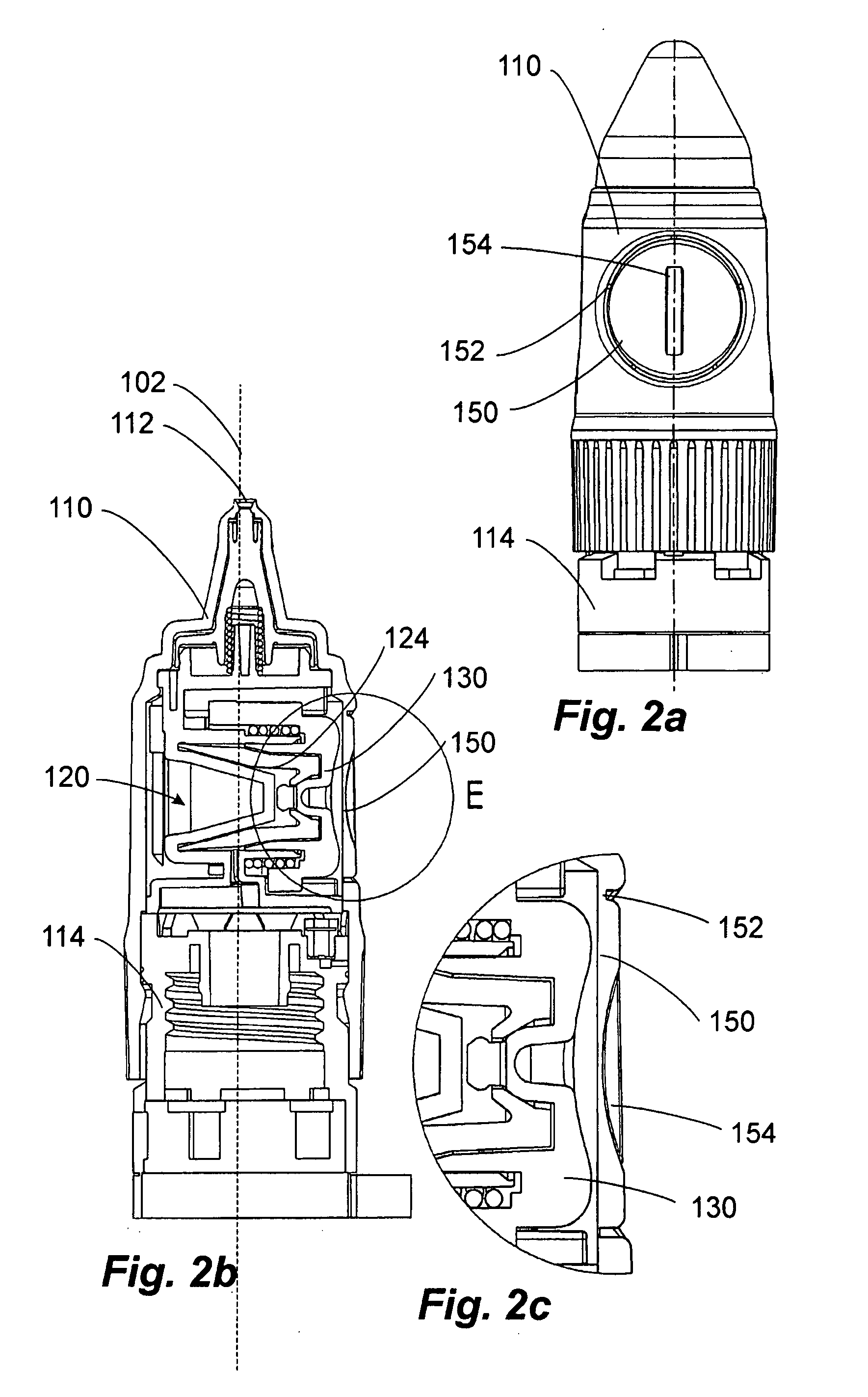
[0013] Securing portions are preferred which are integrally connected to the housing and are connected by destructible connecting portions to other portions of the housing. A securing portion which is integrated in the housing is expedient in particular by virtue of the fact that it is restorable only with great effort and can hence ensure, in particular, the originality of the discharger. It is particularly expedient if the securing portion is connected to the rest of the housing with a plastics film or thin plastics webs, the plastics film or the plastic webs being dimensioned such that the force of the restoring spring is not sufficient to sever it / them without manual assistance. The advantage of the plastics film is that the housing can be kept dust-tight. The removal of the securing portion can be realized, for example, by pressing in the securing portion, this offering the advantage that the actuating device is also thereby pressed in up to its limit position with the smallest pumping chamber volume, so that, following subsequent release, both the securing portion is removed and the pumping chamber is filled with the medium so as to be ready for use.
[0016] However, preference is for a handling means which is a non-round indentation, preferably a longitudinally extending groove. A indentation offers the advantage that it does not adversely enlarge the external shape. This is a considerable advantage, particularly in the case of rotationally symmetric external shapes. A longitudinally extending groove can serve, in particular, for the introduction of a coin, by means of which the securing portion can then be twisted.

Problems solved by technology

It is regarded as a drawback with known dischargers that, because of the actuating device, which is normally provided laterally, they are generally not rotationally symmetric in shape, which constitutes a problem in mechanical handling, particularly with respect to the filling operation.
It is particularly expedient if the securing portion is connected to the rest of the housing with a plastics film or thin plastics webs, the plastics film or the plastic webs being dimensioned such that the force of the restoring spring is not sufficient to sever it / them without manual assistance.

Method used


Image

  • Discharger for a flowable medium
  • Discharger for a flowable medium
  • Discharger for a flowable medium

Examples


Embodiment Construction

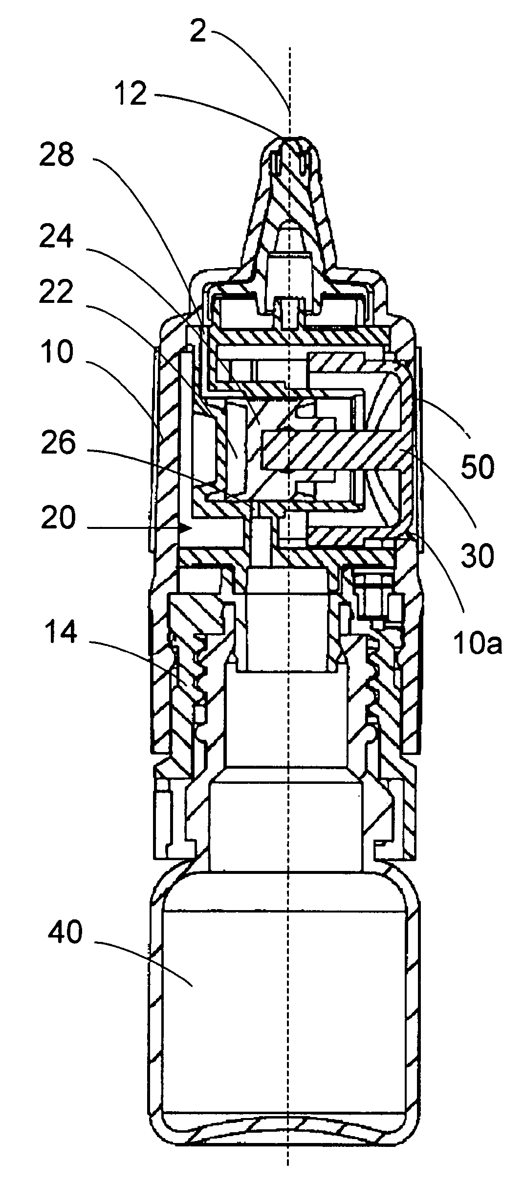
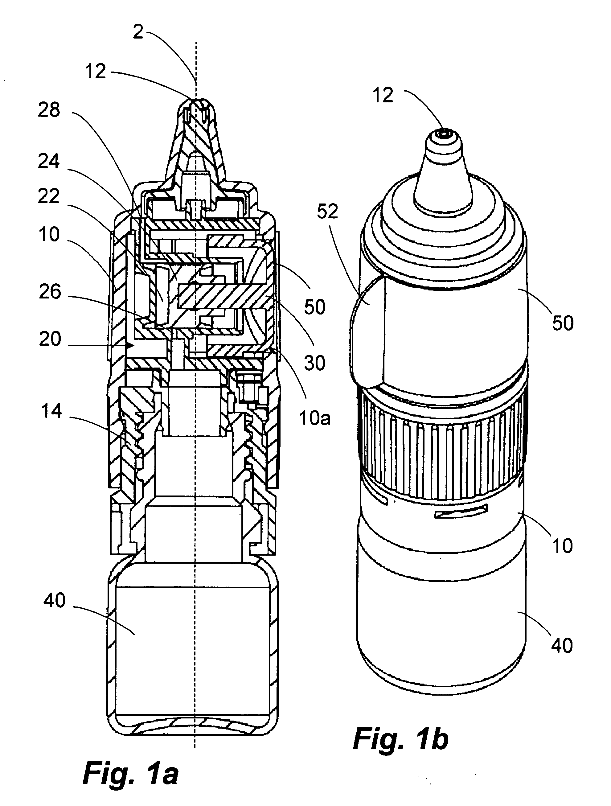
[0021] The first embodiment, which is represented in FIGS. 1a and 1b, has a housing 10, which extends substantially in a principal direction of extent 2. The housing 10 is configured broadly rotationally symmetrically in relation to this principal direction of extent. At an upper end there is provided a discharge opening 12, and at a lower end a fastening device 14 into which a medium container 40 is screwed.

[0022] In the housing 10 there are contained all basic functional elements which are necessary for a discharge process. These comprise a pumping device 20 having a pumping chamber 22 and a piston 24. The pumping chamber is connected by a first feed line 26 to the medium container 40 and by a second feed line 28 to the discharge opening 12. The piston 24 is configured for a piston movement which is orientated transversely to the principal axis of extent 2.

[0023] The piston 24 is fixedly connected to an actuating device 30, which, in an operating state (not represented), juts th...


PUM


Abstract

1. Discharger. 2.1. The invention relates to a discharger for a flowable medium, comprising a discharge opening (112) on the one hand, and a medium container or a fastening device (114) for a medium container on the other hand, which are disposed at opposite ends of the discharger in mutual alignment along a principal direction of extent (102) of the discharger, and a pumping device (120) having a pumping chamber closed off on one side by a piston (124), the piston (124) being configured such that it is longitudinally movable along a pumping direction for the generation of a discharge pressure and the pumping direction forming approximately a right angle with the principal direction of extent (102). 2.2 According to the invention, the piston (124) is operatively connected to an actuating device (130) which can be manually pressed in in the pumping direction and which, in a delivery state of the discharger, is held by a securing element (150) in a pressed-in state in which the pumping chamber has a small volume. 2.3 The discharger according to the invention allows, in particular, an advantageous handling in connection with the assembly.

Description

FIELD OF APPLICATION AND PRIOR ART [0001] The invention relates to a discharger for a flowable medium, in particular for applying the medium into an eye or a nose, comprising a discharge opening on the one hand, and a medium container or a fastening device for a medium container on the other hand, which are disposed at opposite ends of the discharger in mutual alignment along a principal direction of extent of the discharger, and a pumping device having a pumping chamber closed off on one side by a piston, the piston being configured such that it is longitudinally movable along a pumping direction for the generation of a discharge pressure and the pumping direction forming approximately a right angle with the principal direction of extent. [0002] Such dischargers are known from the prior art. They are used, in particular, for cosmetics and medicines. They are usually actuated by means of an actuating device, which is configured for actuation transversely to the principal direction o...

Claims


Application Information

Patent Timeline
IPC IPC(8): B67D5/40B67D7/58
CPCB05B11/0072B05B11/306B05B11/3047B05B11/3002B05B11/1002B05B11/106B05B11/1047
Inventor STADELHOFER, PETERGREINER-PERTH, JUERGENCATER, MIRO
Owner ING ERICH PHEIFFER GMBH & CO KG
Learn More