
Trigger sprayer with integral piston rod and u-shaped spring

a technology of u-shaped springs and piston rods, which is applied in the direction of instruments, liquid transfer devices, single-unit apparatuses, etc., can solve the problems of reducing the overall cost of manufacturing the trigger sprayer, and the cost of recycling prior art trigger sprayers, so as to reduce the manufacturing cost, reduce the cost of components of the trigger sprayer, and recycle more economically

Inactive Publication Date: 2007-09-13
CONTINENTALAFA DISPENSING CO
View PDF18 Cites 13 Cited by
  • Summary
  • Abstract
  • Description
  • Claims
  • Application Information

AI Technical Summary

Benefits of technology

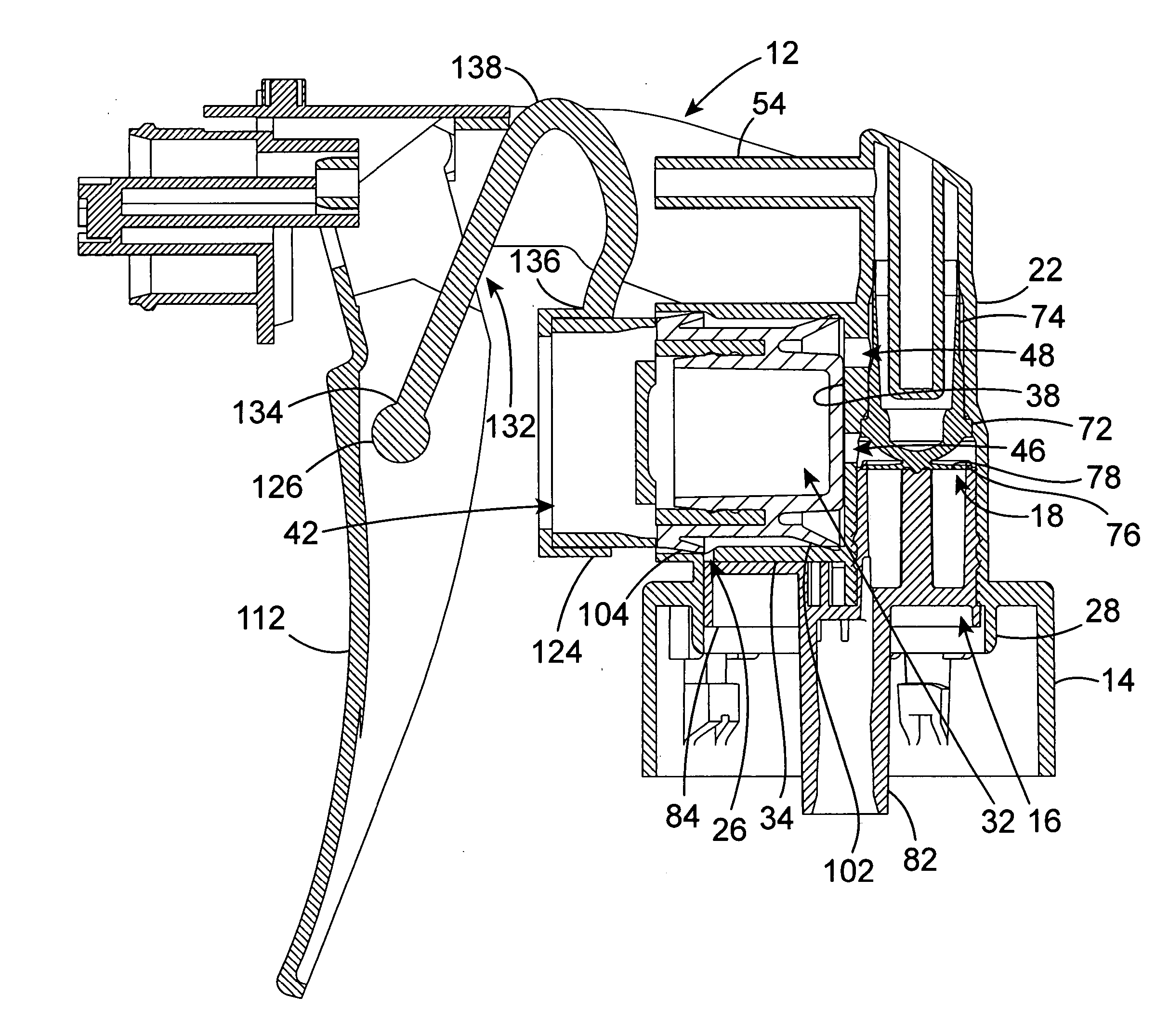
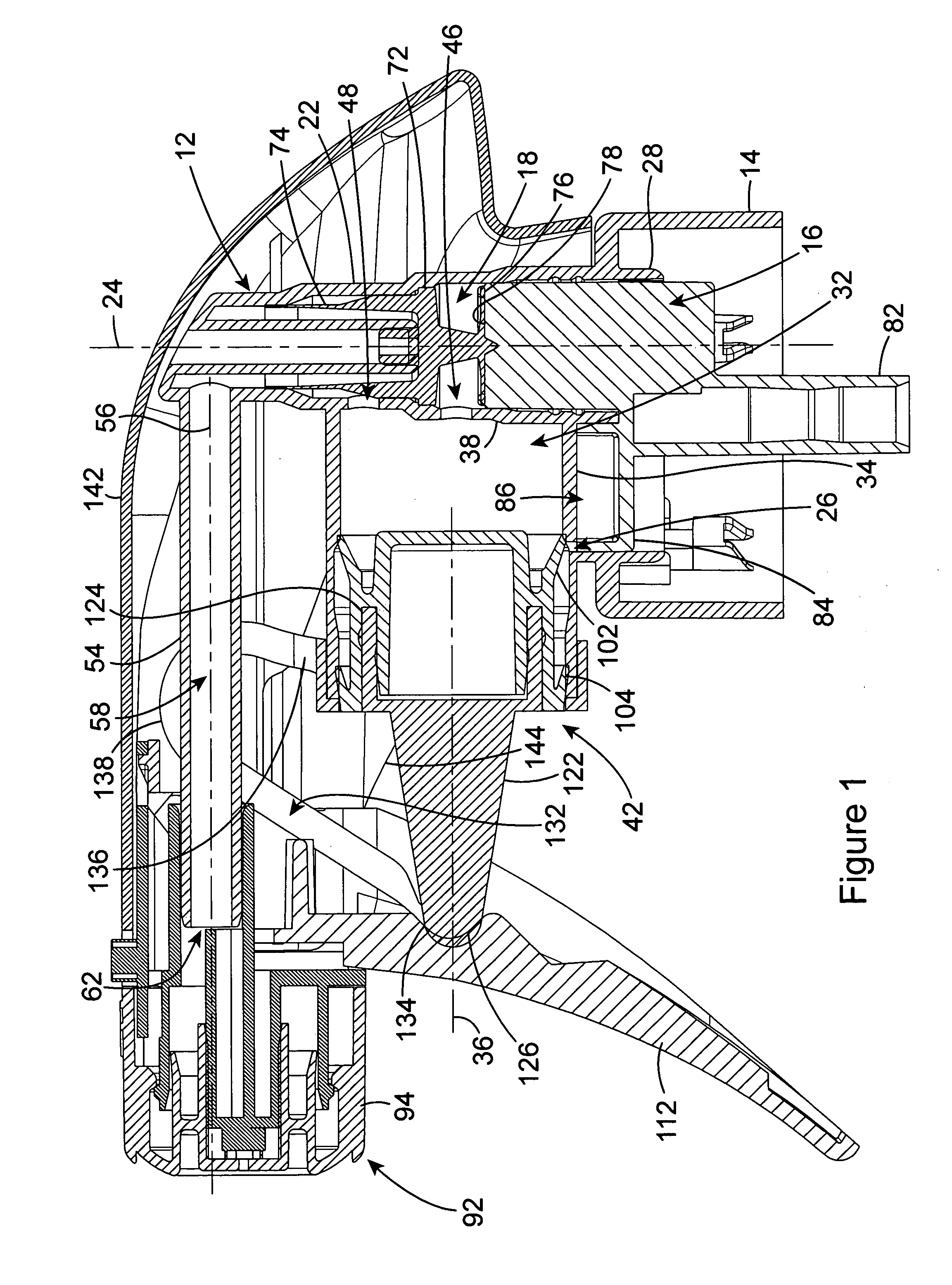
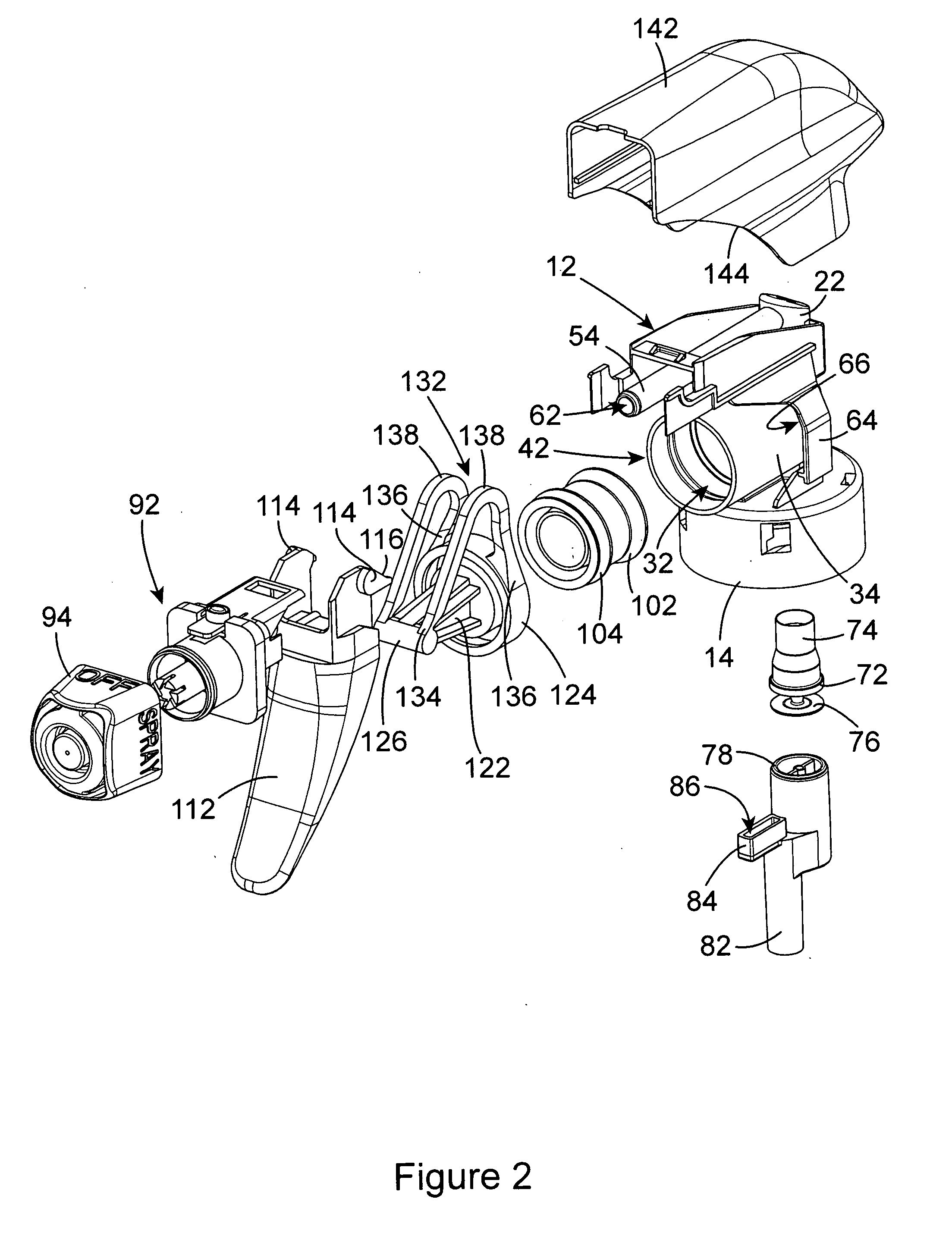
[0015] The trigger sprayer of the present invention achieves the desired objectives of reducing the total number of component parts that go into a trigger assembly, and eliminating the metal coil spring from those component parts. As a result, the trigger sprayer of the invention can be manufactured more cost efficiently, and the recycling of the trigger sprayer is more economical.
[0023] A manually operated trigger is mounted on the sprayer housing for pivoting movement. The trigger is engaged by the fingers of a user's hand holding the trigger sprayer. Squeezing the trigger causes the trigger to move toward the pump chamber, and releasing the squeezing force on the trigger allows the trigger to move away from the pump chamber.
[0027] By providing the U-shaped springs as an integral part of the pump piston rod in lieu of the conventional coiled metal spring positioned in the pump chamber, the component parts of the trigger sprayer are reduced. This results in reduced manufacturing costs.
[0028] In addition, by providing the pair of springs as an integral part of the pump piston rod, the springs are constructed of the same piece of material as the pump piston rod. This eliminates the need for a metal coil spring and enables all of the component parts of the trigger sprayer to be constructed of plastic material. With all of the sprayer parts being constructed of plastic, the trigger sprayer can be recycled more economically.

Problems solved by technology

The manufacturing of each of these individual component parts contributes to the overall cost of manufacturing the trigger sprayer.
However, the cost of recycling prior art trigger sprayers is substantially increased by the need to disassemble a trigger sprayer to remove the metal coil spring.

Method used


Image

  • Trigger sprayer with integral piston rod and u-shaped spring
  • Trigger sprayer with integral piston rod and u-shaped spring
  • Trigger sprayer with integral piston rod and u-shaped spring

Examples


Embodiment Construction

[0034] As stated earlier, the novel design of the trigger sprayer of the present invention enables each of the component parts of the trigger sprayer to be constructed of a resilient, plastic material. In addition, the novel construction enables several component parts to be constructed of one, monolithic piece of material, that were in the past constructed of several separate pieces. This results in a reduction in the manufacturing costs. The all plastic construction of the trigger sprayer enables the sprayer to be more economically recycled after use.

[0035] Several component parts of the trigger sprayer are found in the typical construction of a trigger sprayer, and therefore these component parts are described only generally herein. It should be understood that although the component parts are shown in the drawing figures and are described as having a certain construction, other equivalent constructions of the component parts are known. These other equivalent constructions of tr...


PUM


Abstract

A manually operated trigger sprayer is constructed with a reduced number of parts and in a novel manner in which all of the component parts of the sprayer are constructed of a plastic material. The construction of the trigger sprayer replaces the conventional metal coil spring in the pump chamber with a pair of plastic springs having inverted U-shaped configurations that are integral with the piston rod and are positioned outside the pump chamber. Constructing all of the sprayer parts of a plastic material enables a cost efficient recycling of the parts, which does not require disassembling the parts to remove a metal spring.

Description

BACKGROUND OF THE INVENTION [0001] (1) Field of the Invention [0002] The present invention pertains to the construction of a manually operated trigger sprayer in which all of the component parts of the sprayer are constructed of a plastic material. The construction of the trigger sprayer replaces the conventional metal coil spring with a plastic U-shaped spring that is an integral part of the pump piston rod. Constructing all of the sprayer parts of a plastic material enables a cost efficient recycling of the parts that does not require disassembling of the parts to remove the metal spring. [0003] (2) Description of the Related Art [0004] Handheld and hand pumped liquid dispensers commonly known as trigger sprayers are used to dispense many household products and commercial cleaners. Trigger sprayers have been used to dispense household cleaning or cooking liquids and have been designed to selectively dispense the liquids in a spray, stream, or foaming discharge. The trigger sprayer...

Claims


Application Information

Patent Timeline
Patent Type & Authority Applications(United States)
IPC IPC(8): B65D88/54B67D5/40B67D7/58
CPCB05B11/0029B05B11/3011B05B11/3077B05B11/3074B05B11/3064B05B11/1011B05B11/1064B05B11/1074B05B11/1077
Inventor CLYNES, WALTER J.NELSON, PHILIP L.
Owner CONTINENTALAFA DISPENSING CO
Learn More