
Method for operating an internal combustion engine

Inactive Publication Date: 2007-09-13
DAIMLER AG
View PDF4 Cites 3 Cited by
  • Summary
  • Abstract
  • Description
  • Claims
  • Application Information

AI Technical Summary

Benefits of technology

[0008] In order to optimize combustion, according to the invention, a second adjustment or adaptation of the EGR rate is carried out as a function of a noise level of the combustion. In this way, the EGR rate can be varied by means of the noise level in the combustion chamber of the internal combustion engine as a function of the load point and can be rapidly adjusted. Stable operation with reduced nitrogen oxide and particulate emissions in the exhaust gas, and with high efficiency, is therefore ensured in particular in the new combustion methods of diesel internal combustion engines.
[0009] In one preferred embodiment of the invention, a determination of the noise level is carried out by means of a sensor. The sensor is arranged, for example, on the cylinder head of the internal combustion engine. The sensor is preferably arranged at a suitable point on or in the combustion chamber wall for detecting the combustion noises. Alternatively, a combustion chamber sensor can be attached to each cylinder of the internal combustion engine, so that, if required, targeted and separate adaptation or adjustment of the EGR rate can be carried out for each individual cylinder. For this purpose, a piezoelectric body-borne noise pick-up can be used as a sensor. It is therefore possible to provide for advantageous adaptation or control of the EGR rate in particular in conjunction with the modern diesel internal combustion engines, so that nitrogen oxide emissions can be considerably reduced. In addition, the invention also makes it possible to keep the combustion noise low.
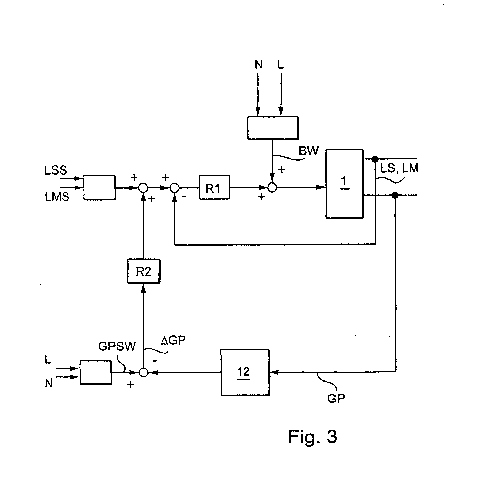
[0012] According to a further embodiment of the invention, the second adjustment or adaptation of the exhaust gas recirculation rate is carried out as a function of a correction value which is formed from a difference between the determined noise level and a nominal noise level. This makes it possible to provide for precise and relatively fast control of the EGR rate, and therefore permits optimized combustion. The nominal noise level is preferably determined as a function of a load-point-dependent nominal exhaust gas recirculation rate or as a function of the speed and / or load.

Problems solved by technology

In modern internal combustion engines, in particular in diesel internal combustion engines, a control system of this type does not provide the required accuracy, since the new combustion methods demand rapid and load-point-dependent EGR regulation.

Method used


Image

  • Method for operating an internal combustion engine
  • Method for operating an internal combustion engine
  • Method for operating an internal combustion engine

Examples


Embodiment Construction

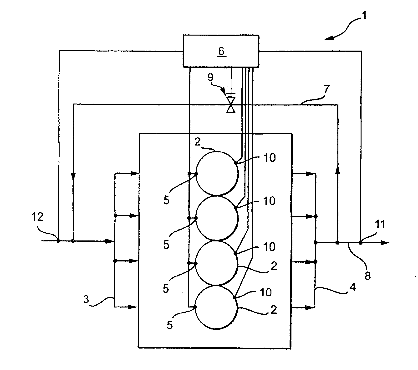
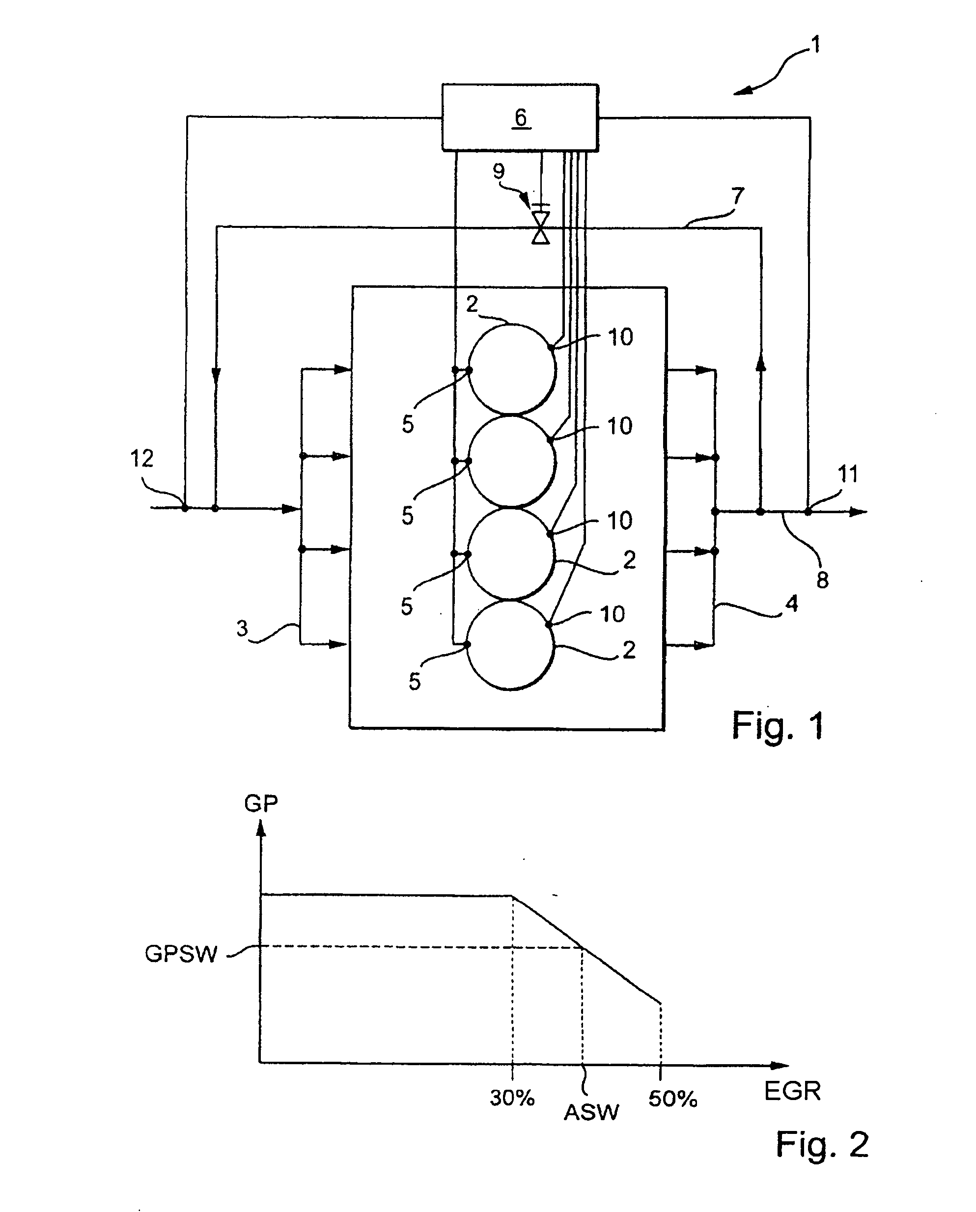
[0018] The internal combustion engine 1 illustrated in FIG. 1 has a plurality of cylinders 2, each including a combustion chamber delimited between a cylinder head and a piston in each cylinder 2. Fuel is supplied to the combustion chambers, and is mixed there with combustion air. Auto-ignition of the mixture which is formed takes place by means of compression, though the mixture can alternatively be ignited by a spark. The present invention is in particular not restricted to a specific type of internal combustion engine. The combustion air is supplied to the combustion chamber in a known way by means of an intake manifold 3, to which all the cylinders 2 are connected by means of their intake ducts (not illustrated). Combustion exhaust gases are discharged from the cylinders 2 via exhaust ducts (not illustrated) which open out into a common exhaust gas collecting line 4. In order to supply to the cylinder the required fuel, a fuel injector 5 is arranged in each cylinder 2, which fue...


PUM


Abstract

In a method for operating an internal combustion engine, in particular an auto-ignition internal combustion engine, having at least one combustion chamber in which an air / fuel mixture is formed, and recirculated exhaust gas is admixed to the combustion air, a base setting of the exhaust gas recirculation rate is established as a function of a first characteristic operating variable, the exhaust gas recirculation rate is adjusted depending on at least one of the first and a second characteristic operating variable, and, in order to optimize combustion, the exhaust gas recirculation rate is adjusted a second time on the basis of a combustion noise measurement.

Description

[0001] This is a Continuation-In-Part application of pending international patent Application PCT / EP2005 / 008187 filed 07 / 28 / 05 and claiming the priority of German patent application 10 2004 037 053.2 filed Jul. 30, 2004.BACKGROUND OF THE INVENTION [0002] The invention relates to a method for operating an internal combustion engine, in particular an internal combustion engine with compression ignition having at least one combustion chamber for burning therein a mixture of fuel and air to which exhaust gas is admixed. [0003] It is generally known in internal combustion engines to re-circulate exhaust gas (EGR) in order to reduce the exhaust gas emissions of the internal combustion engine. Here, part of the exhaust gas from the exhaust side of the internal combustion engine is returned to the intake side of the internal combustion engine and is admixed to the combustion air. [0004] In a conventional embodiment of an EGR control system, a base setting of the EGR rate is adjusted for exa...

Claims


Application Information

Patent Timeline
IPC IPC(8): F02M7/00F02M25/07F02B47/08F02D41/00F02D41/14
CPCF02D35/023F02D41/0052F02D41/0057F02D41/1498Y02T10/47F02D41/3035F02D2041/1419F02D2200/025F02D41/18Y02T10/40
Inventor AMMANN, MARKUSCHRISTNER, BERNDFEKETE, NICHOLASKLINGEBIEL, MATTHIASPFAFF, RUEDIGER
Owner DAIMLER AG
Learn More