
DVI link with circuit and method for test

a digital visual interface and circuit technology, applied in the field of digital visual interface links, can solve the problems of difficult and cumbersome test mode of dvi links, incompatibility of prbs patterns with encoded digital visual information,

Active Publication Date: 2007-09-06
MICRON TECH INC
View PDF21 Cites 3 Cited by
  • Summary
  • Abstract
  • Description
  • Claims
  • Application Information

AI Technical Summary

Problems solved by technology

One problem with the BERT method of testing the DVI link is that the PRBS pattern is incompatible with encoded digital visual information that is transmitted over the DVI link during its normal operation.
The incompatibility makes the test mode of the DVI link difficult and cumbersome.

Method used


Image

  • DVI link with circuit and method for test
  • DVI link with circuit and method for test
  • DVI link with circuit and method for test

Examples


Embodiment Construction

[0014] In the following detailed description of exemplary embodiments of the present invention, reference is made to the accompanying drawings which form a part hereof, and in which are shown by way of illustration specific exemplary embodiments in which the present invention may be practiced. These embodiments are described in sufficient detail to enable those skilled in the art to practice the present invention, and it is to be understood that other embodiments may be utilized and that logical, mechanical, electrical and other changes may be made without departing from the spirit or scope of the present invention. The following detailed description is, therefore, not to be taken in a limiting sense, and the scope of the present invention is defined only by the claims.

[0015] In this description a digital signal of 1 may also be called a high signal and a digital signal of 0 may also be called a low signal. In this description, unless otherwise specified, a line comprises a transmi...


PUM


Abstract

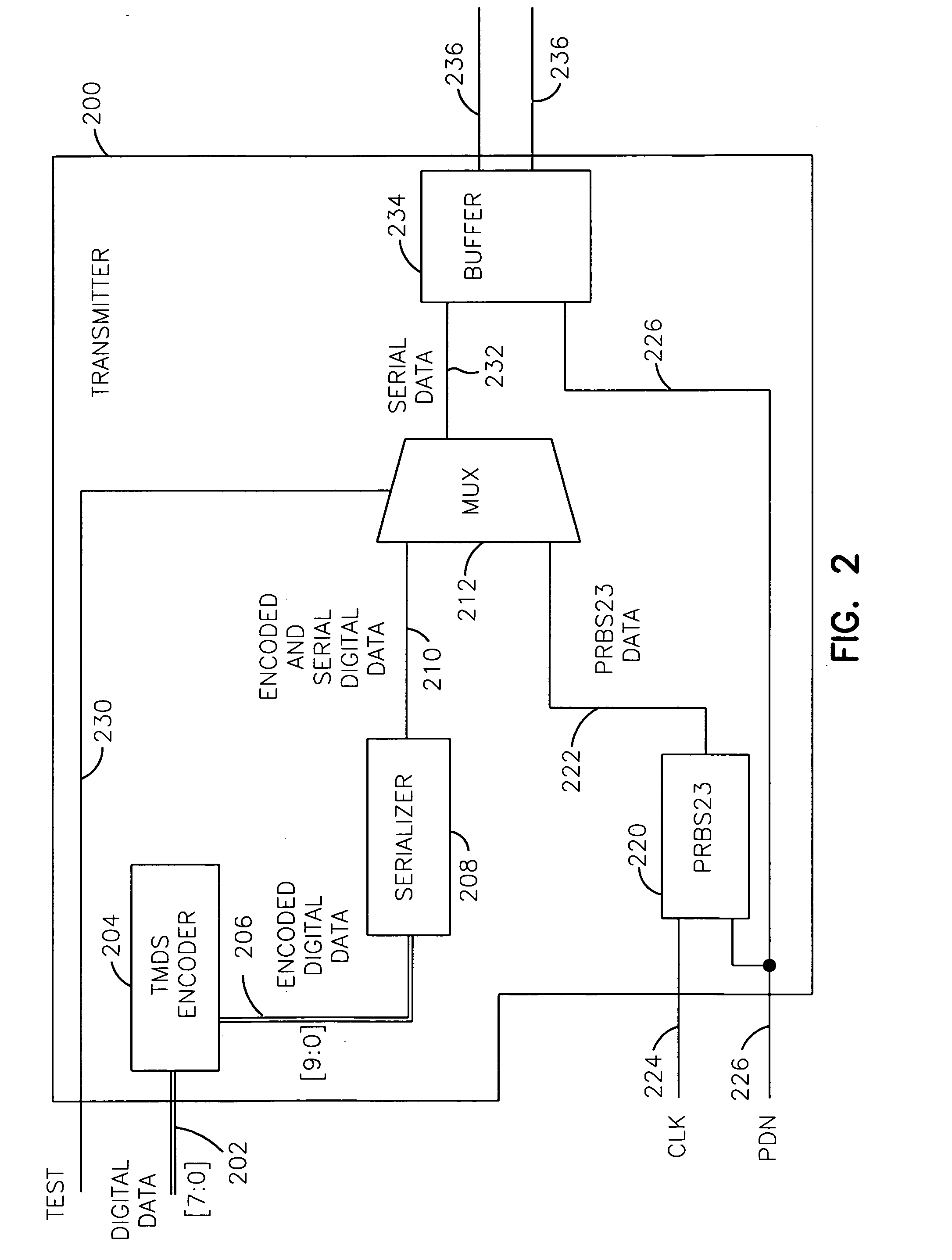
An embodiment includes encoding digital data into encoded digital data in a transition minimized differential signaling encoder, serializing the encoded digital data into encoded and serial digital data in a serializer, generating test data in a pseudo-random binary sequence generator circuit, transmitting the encoded and serial digital data through a multiplexer to a transmission medium in a normal mode of operation, and transmitting the test data through the multiplexer to the transmission medium in a test mode of operation. The encoder, the serializer, the sequence generator circuit, and the multiplexer may be fabricated in a single integrated circuit chip. The test data may be pseudo-random binary sequence data. The digital data may include data to generate colors in a visual image, and the encoded and serial digital data may be received, deserialized, decoded, and displayed in a display unit.

Description

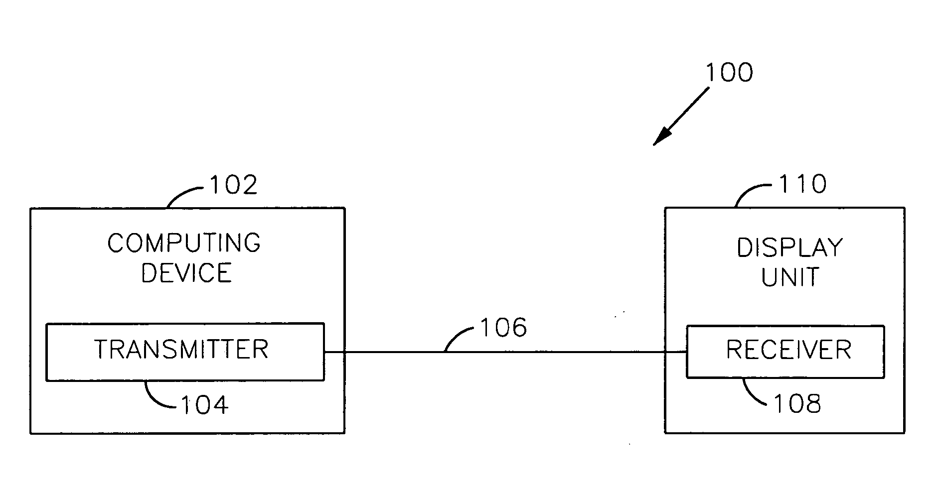
CROSS REFERENCE TO RELATED APPLICATIONS [0001] This application is a Continuation of U.S. application Ser. No. 10 / 163,058, filed on Jun. 4, 2002, which claims priority under 35 U.S.C. 119 from British Application No. 0130201.7 filed Dec. 17, 2001, which applications are incorporated herein by reference.FIELD OF THE INVENTION [0002] The present invention relates generally to digital visual interface links, and more particularly, to a digital visual interface link with a circuit and method for testing the link. BACKGROUND [0003] A digital visual interface (DVI) link is a high-speed digital connection to transmit digital visual information including data and / or instructions. The DVI link is used primarily to transmit digital visual information between a computing device and a display unit such as a monitor that displays the digital visual information. An advantage of the DVI link over analog links is that the digital visual information in the DVI link remains in the digital domain to s...

Claims


Application Information

Patent Timeline
Patent Type & Authority Applications(United States)
IPC IPC(8): G01R31/28G01R31/08H04B10/08H04L1/00H04L1/24H04N7/52H04N11/04H04N17/00
CPCH04L1/244H04N17/004H04N11/04H04N7/52
Inventor QUINLAN, SION C.WARNER, DAVID J.
Owner MICRON TECH INC
Learn More