
Fan-In Leadframe Semiconductor Package

a semiconductor package and fan technology, applied in liquid degasification, separation processes, lighting and heating apparatus, etc., can solve the problems of unburned carbon floating, affecting the workability of concrete, and affecting the effect of a black part occurring in the connecting portion of concr

Active Publication Date: 2007-08-30
JFE PROJECT ONE CO LTD +2
View PDF5 Cites 16 Cited by
  • Summary
  • Abstract
  • Description
  • Claims
  • Application Information

AI Technical Summary

Benefits of technology

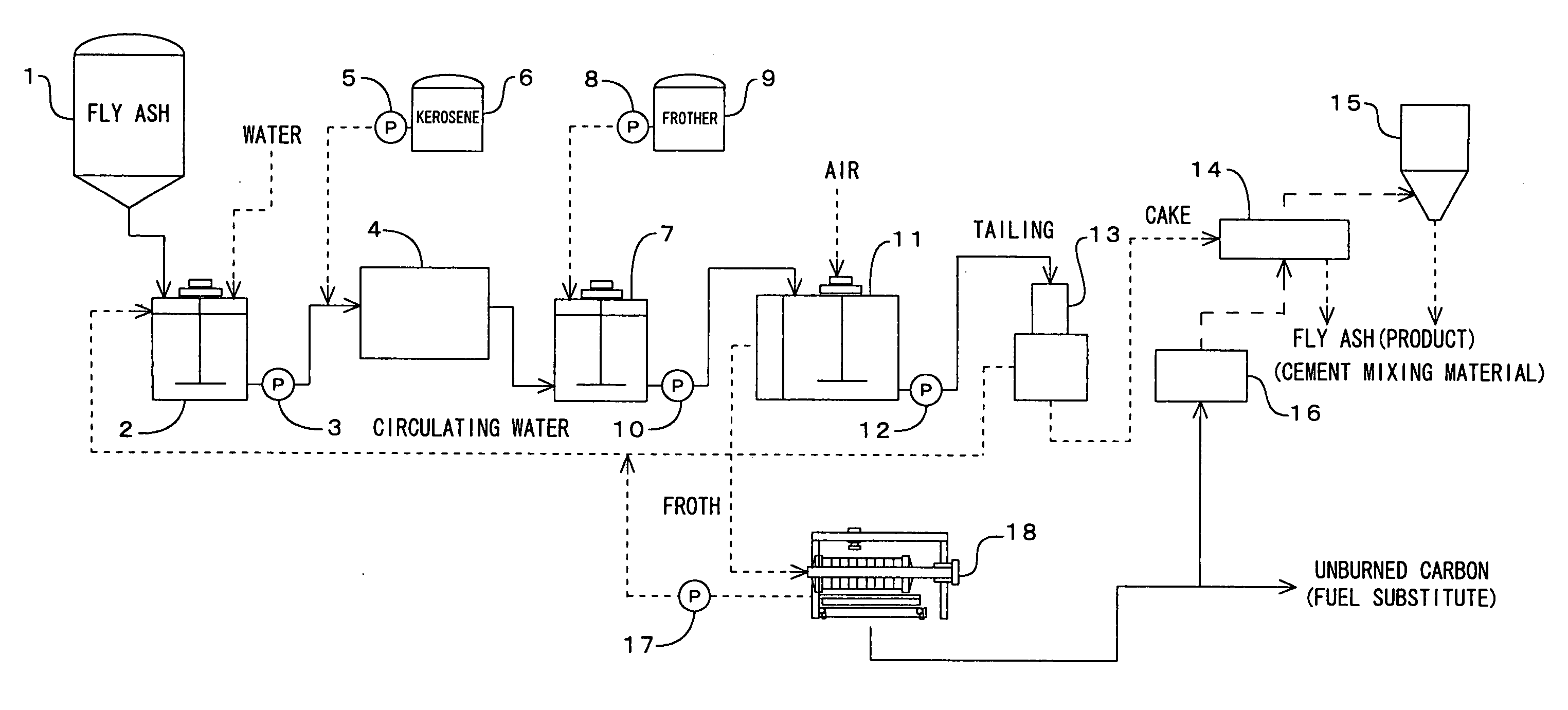
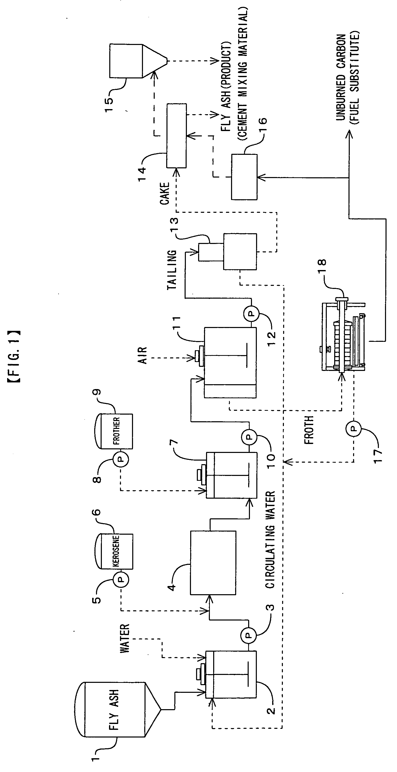
[0011] With this invention, by adding shearing force to original fly ash slurry, which contains the unburned carbon and to which collector is added before flotation process, through a submerged agitator having a rotation shaft, which penetrates a cylindrical main body in the axial direction thereof, plurality of chambers divided and formed in the axial direction thereof in the inside of the main body, and an agitating vane, which is fixed to the rotation shaft and rotates in each chamber, each of the unburned carbon in slurry, true fly ash, and the collector can not only raise the distributed effect but transitionally generate activity energy (surface energy) on the surface of each distributed particle. In the process which makes this transitional surface energy calm down, the surface of unburned carbon particles, which becomes more oleophilicitized, and the surface of collector particles stick with each other, and mutual surface energy is lowered. The surface of true fly ash particles, which becomes more hydrophilicitized, adapts itself to water further, it distributes in water and the particles concerned lower the surface energy. As a result, the fly ash particles, to which the collector is adhered on the surface thereof and of which surface is modified, stably raise its oleophilicity and its flotation separation performance is raised in a latter flotation process, so that the fly ash particles distribute in water, and are efficiently separated with the true fly ash which becomes a flotation tailing. As a result, unburned carbon can efficiently be removed from the original fly ash slurry. When shearing force is not applied to the fly ash slurry and the collector and surface modification is not performed to the slurry and the collector, fly ash with 5.0% of unburned carbon can be reduced its unburned carbon content to only approximately 2%. On the other hand, by adding shearing force and performing surface modification, unburned carbon of the fly ash can considerably reduced, and fly ash with approximately 0.5% of unburned carbon can be obtained. In addition, in this case, generally used collector such as kerosene can be used, and a small amount (about 15%) is sufficient for the collector to the quantity of unburned carbon. This makes it possible to reduce the amount of collector used, to allow little kerosene etc. to remain in the fly ash as a product and to make post-processing after the flotation process easy.
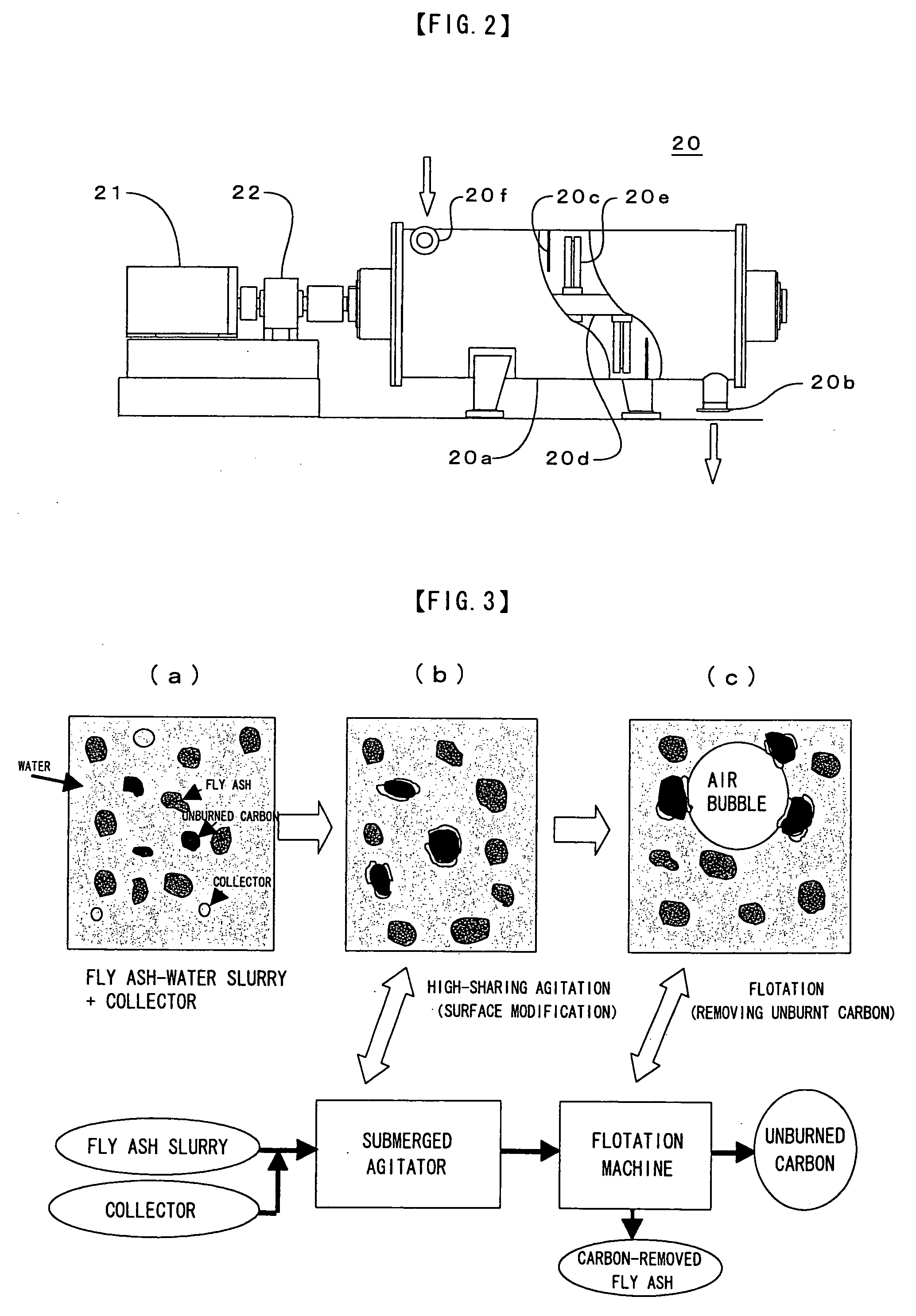
[0036] On the other hand, as shown in FIG. 3(a), when shearing force is added to the slurry and the collector to modify the surfaces thereof, as shown in FIG. 3(b), unburned carbon is adsorbed to the collector. Then, when performing flotation separation with a flotation machine, as shown in FIG. 3(c), the unburned carbon adsorbed to the collector is adhered to air bubbles and rises together with the bubbles. Thus, the flotation separation performance of the unburned carbon can be improved. Meanwhile, when applying shearing force to the slurry and the collector through the high-speed shearing mixer 20, 0.7-10 kWh / m3 more preferably 0.9-1.8 kWh / m3 of agitating force per unit quantity of slurry is added.

Problems solved by technology

However, when fly ash is used as concrete admixture, unburned carbon of fly ash will absorb AE water reducing agent etc., and will reduce the workability of the concrete.
And, at the time of placing of the concrete, unburned carbon comes floating and there is harmful influence of a black part occurring in the connecting portion of the concrete.
Further, when there was much unburned carbon of fly ash, there was also a problem that the quality of an artificial lightweight aggregate deteriorated.
Therefore, only fly ash with little unburned carbon was used for the materials of cement etc., the fly ash with high unburned carbon content could not be used effectively and was processed for reclamation as industrial waste.

Method used


Image

  • Fan-In Leadframe Semiconductor Package
  • Fan-In Leadframe Semiconductor Package
  • Fan-In Leadframe Semiconductor Package

Examples


embodiment 1

[0039] 1000 ml of water and 200 g of fly ash (containing 5.0 weight percent of unburned carbon) are mixed while being agitated to produce slurry. To the slurry is added kerosene in the range of 0.6-8.0 ml and is agitated at 0-1164 rpm by the high-speed shearing mixer showing in FIG. 2 to add shearing force to the slurry and the kerosene, and unburned carbon of the fly ash is made to be hydrophobic.

[0040] After the process of hydrophobic, the slurry is supplied to a flotation machine, and 0.5 mg of MIBC (methyl isobutyl carbinol) as a frother is added to the slurry to make the unburned carbon adhere to air bubbles and rise. These floating air bubbles are taken out as overflow. This process has been performed for 5 minutes.

[0041] The relation of the rotational frequency of the high-speed shearing mixer and the unburned carbon of fly ash (product) and fly ash (product) remaining inside of a flotation tub is shown in FIG. 4. Showing this graph, without agitation (the rotational freque...

embodiment 2

[0042] 1000 ml of water and 200 g of fly ash (containing 5.0 weight percent of unburned carbon) are mixed while being agitated to produce slurry. To the slurry is added kerosene in the range of 0.6-8.0 ml and is agitated at 873 rpm by the high-speed shearing mixer showing in FIG. 2 to add shearing force to the slurry and the kerosene, and unburned carbon of the fly ash is made to be hydrophobic.

[0043] After the process of hydrophobic, the slurry is supplied to a flotation machine, and 0.5 mg of MIBC as a frother is added to the slurry to make the unburned carbon adhere to air bubbles and rise. These floating air bubbles are taken out as overflow. This process has been performed for 5 minutes.

[0044] The relation of the amount of kerosene added and the unburned carbon of fly ash (product) and fly ash (product) remaining inside of a flotation tub that is shown in FIG. 5. This graph shows that the unburned carbon of fly ash (product) reaches to 0.5% or less in the oil-adding ratio of ...


PUM

PropertyMeasurementUnit
weight percentaaaaaaaaaa
weightaaaaaaaaaa
shearing forceaaaaaaaaaa

Abstract

Unburned carbon is efficiently removed from fly ash, and effective utilization of the fly ash and removed unburned carbon is attained. Water is added to fly ash to thereby obtain a slurry. A collector is added to the slurry, and shearing force is applied to the slurry and collector to thereby attain a surface modification. The mixture is subjected to flotation operation at which unburned carbon of fly ash is attached to froths and surfaced. The application of shearing force to the slurry and collector can be carried out by means of a submerged agitator whereby an agitation power of 0.7 to 10 kWh / m3 is applied per unit quantity of slurry. The fly ash concentration of the slurry is in the range of 3 to 50 wt. %, and the amount of collector added is in the range of 5 to 100 wt. % based on the amount of unburned carbon of fly ash. The unburned carbon separated by flotation can be used as fuel, and the fly ash (product) having its unburned carbon content reduced to 1 wt. % or below can be used as a cement mixing material or a raw material for production of lightweight aggregate.

Description

TECHNICAL FIELD [0001] The present invention relates to a method of removing unburned carbon from fly ash, and more particularly to a method of efficiently removing unburned carbon from the fly ash generated in coal firing power plants and so on and efficiently using the fly ash and the removed unburned carbon. BACKGROUND ART [0002] Fly ash generated in coal firing power plants etc. is used for materials for cement and artificial lightweight aggregates, concrete admixture, etc. However, when fly ash is used as concrete admixture, unburned carbon of fly ash will absorb AE water reducing agent etc., and will reduce the workability of the concrete. And, at the time of placing of the concrete, unburned carbon comes floating and there is harmful influence of a black part occurring in the connecting portion of the concrete. Further, when there was much unburned carbon of fly ash, there was also a problem that the quality of an artificial lightweight aggregate deteriorated. Therefore, only...

Claims


Application Information

Patent Timeline
Patent Type & Authority Applications(United States)
IPC IPC(8): F23J1/00B03D1/02B03D1/10B03D1/12B09B3/00
CPCB03D1/02C04B18/08C04B20/02Y02W30/91B03D1/10B03D1/12
Inventor SAITO, SHINICHIROABE, KAZUOKIMOTO, KOSUKEMURATA, TOSHIAKI
Owner JFE PROJECT ONE CO LTD
Learn More