Analyte sensor
an analyte sensor and sensor technology, applied in the field of membranes, can solve the problems of current use devices that cannot provide data safely and reliably for certain periods of tim
- Summary
- Abstract
- Description
- Claims
- Application Information
AI Technical Summary
Benefits of technology
Problems solved by technology
Method used
Image
Examples
example 1
uctured Sensor Construction
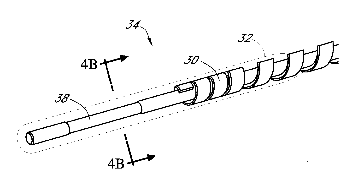
[0411] A short term (transcutaneous) sensor was built by providing a platinum wire, vapor-depositing the platinum with Parylene to form an insulating coating, helically winding a silver wire around the insulated platinum wire (to form a “twisted pair”), masking sections of electroactive surface of the silver wire, vapor-depositing Parylene on the twisted pair, chloridizing the silver electrode to form silver chloride reference electrode, and removing a radial window on the insulated platinum wire to expose a circumferential electroactive working electrode surface area thereon, this assembly also referred to as a “parylene-coated twisted pair assembly.”
[0412] An electrode domain was formed over the parylene-coated twisted pair assembly by coating the assembly with a polyurethane-latex dispersion (Bayhydrol® 123 available from Bayer Material Sciences, Pittsburgh, Pa., USA) crosslinked with EDC in the presence of PVP; followed by curing at about 50° C. An enz...
example 2
PLURONIC® F-127 Cell Impermeable Domain
[0413] 30 g of PLURONIC® F-127 (PF-127) was dissolved under stirring in 100 g of anhydrous acetone at 40° C. 13 g of acetone was added to 37.3 g of the PF-127 solution followed by adding 4.8 g of dicumyl peroxide (DCP). 40 g of MED-4840 was mixed in a speed mixer at a speed of 3300 rpm for 60 seconds. The MED-4840 mixture was then placed in a motorized mechanical mixer equipped with a spiral dough hook. The mixture was stirred at low speed for 30 s. The stirring speed was then increased to medium-low and the PF-127 / DCP solution was added at a rate of 3.5-4.0 g every 30 seconds. After all of the PF-127 / DCP solution was added, the mixture was stirred at medium speed for 3 minutes. The mixture was then placed in a Speed Mixer and mixed at 3300 rpm for 60 seconds. Additional acetone was added (repeatedly), followed by stirring, until the desired viscosity was reached.
[0414] 5-10 nL of the mixture was placed in an evenly distributed line between th...
example 3
PLURONIC® F-127 Diffusion Resistance Domain on Implanted Sensor
[0415] A MED-4840 / PLURONIC® F-127 membrane was manufactured using 8.4% PLURONIC® and 1.8% of a DCP cross-linking agent. This membrane was placed over a two-layer membrane having an enzyme domain and an electrode domain. The combined membrane layers were placed on a wholly implantable glucose sensor. The sensor was sterilized and implanted into a diabetic rat model. FIG. 6 is a graph depicting the resulting glucose sensor measurements over the course of approximately two months. The small points in FIG. 4 depict glucose concentrations measured by the sensor and the large points depict glucose concentrations measured by separate blood glucose assays. The graph indicates a close correlation between the sensor glucose measurements and the blood glucose measurements.
PUM
 Abstract
Description
Claims
Application Information
 - R&D
- Intellectual Property
- Life Sciences
- Materials
- Tech Scout
- Unparalleled Data Quality
- Higher Quality Content
- 60% Fewer Hallucinations
Browse by: Latest US Patents, China's latest patents, Technical Efficacy Thesaurus, Application Domain, Technology Topic, Popular Technical Reports.
© 2025 PatSnap. All rights reserved.Legal|Privacy policy|Modern Slavery Act Transparency Statement|Sitemap|About US| Contact US: help@patsnap.com


