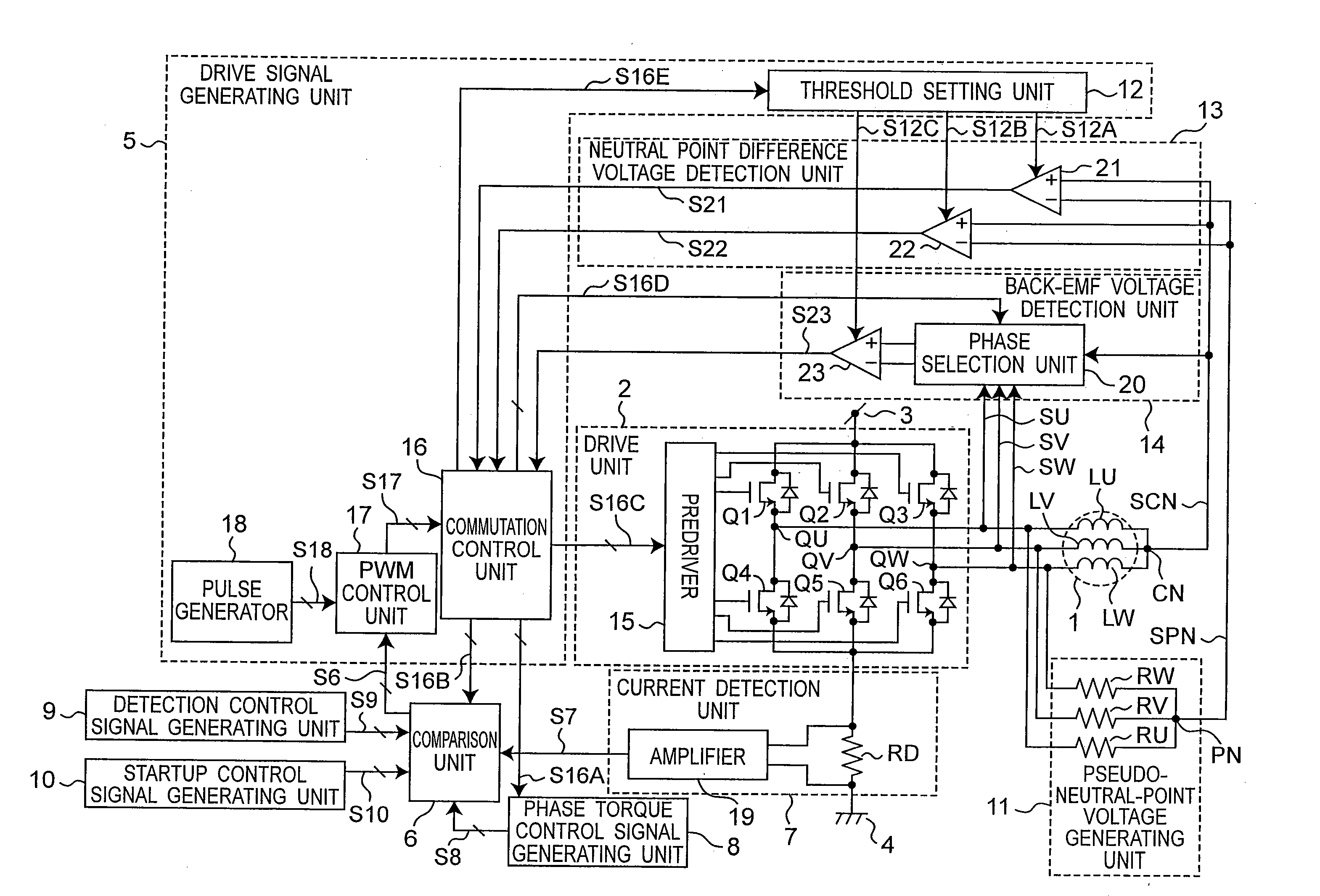
Motor drive device
a three-phase brushless, motor technology, applied in the direction of motor/generator/converter stopper, electronic commutator, dynamo-electric converter control, etc., can solve the problems of insufficient phase characteristics control, pulse current rise, and difficult to accurately read peak pulse current flow, etc., to achieve the effect of reducing the number of motors, and improving the reliability of neutral point difference voltag
- Summary
- Abstract
- Description
- Claims
- Application Information
AI Technical Summary
Benefits of technology
Problems solved by technology
Method used
Image
Examples
embodiment 1
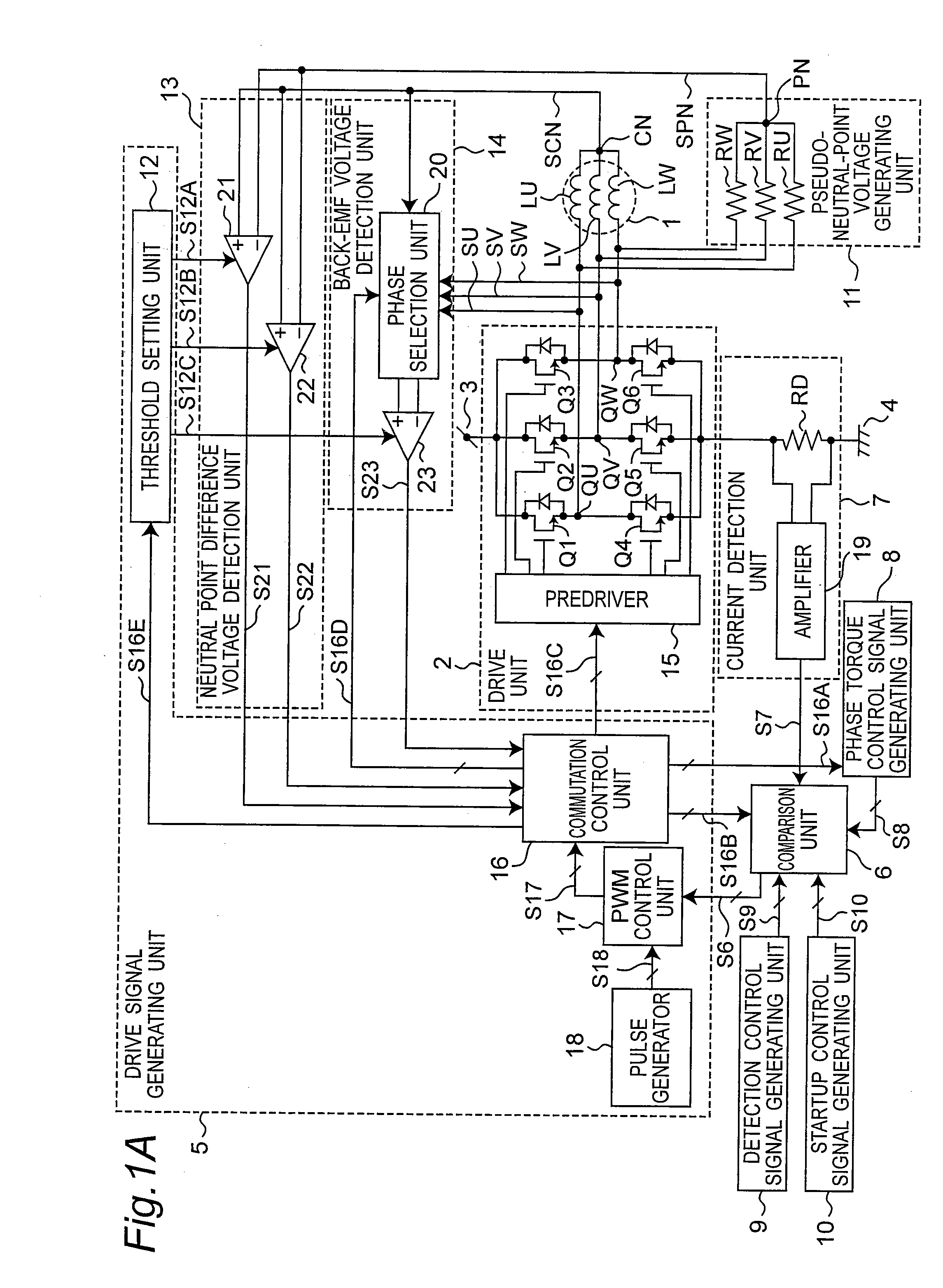
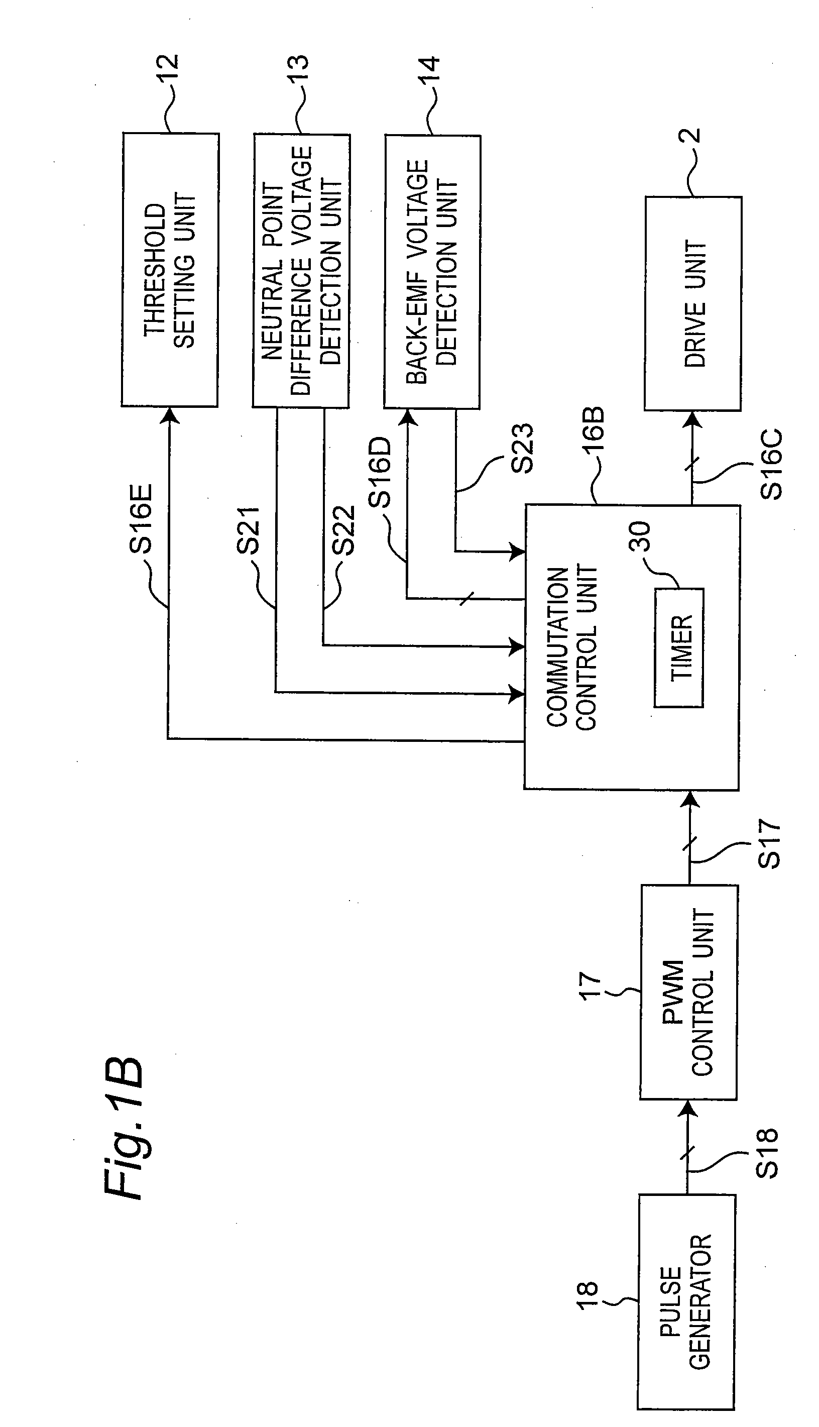
[0064]FIG. 1A is a circuit block diagram of a motor drive device according to a first embodiment of the invention. The motor drive device shown in FIG. 1A has a motor 1, a drive unit 2, a drive signal generating unit 5, a comparison unit 6, a current detection unit 7, a phase torque control signal generating unit 8, a detection control signal generating unit 9, a startup control signal generating unit 10, a pseudo-neutral-point voltage generating unit 11, a neutral point difference voltage detection unit 13, and a back electromotive force (back-EMF) voltage detection unit 14.
[0065]The motor 1 has a three-phase fixed stator and a rotor that rotates around the stator. A three-phase motor 1 is used as the motor in this first embodiment of the invention, but the invention can be applied to any N-phase motor where N is an integer of two or more. The U-phase motor winding LU, V-phase motor winding LV, and W-phase motor winding LW are connected in common at neutral point CN, and the other ...
second embodiment
[0436]The first embodiment has been described using two energized phases. This second embodiment of the invention uses three energized phases and is described below with particular reference to the difference with the first embodiment. Other aspects of the arrangement, operation, and effect are the same as in the first embodiment above.
[0437]FIG. 20 shows the circuit arrangement of the motor drive device according to a second embodiment of the invention. The motor drive device shown in FIG. 20 has a motor 1, a drive unit 2, a drive signal generating unit 5, a comparison unit 6, a current detection unit 7, a phase torque control signal generating unit 8, a detection control signal generating unit 9, a startup control signal generating unit 10, a pseudo-neutral-point voltage generating unit 11, a neutral point difference voltage detection unit 13A, and a back-EMF voltage detection unit 14A.
[0438]The motor 1 has a three-phase fixed stator and a rotor that rotates around the stator. The...
PUM
 Abstract
Description
Claims
Application Information
 - R&D
- Intellectual Property
- Life Sciences
- Materials
- Tech Scout
- Unparalleled Data Quality
- Higher Quality Content
- 60% Fewer Hallucinations
Browse by: Latest US Patents, China's latest patents, Technical Efficacy Thesaurus, Application Domain, Technology Topic, Popular Technical Reports.
© 2025 PatSnap. All rights reserved.Legal|Privacy policy|Modern Slavery Act Transparency Statement|Sitemap|About US| Contact US: help@patsnap.com


