
Measurement system optimization

a measurement system and optimization technology, applied in the field of measurement systems, can solve the problems of missing key issues in the optimization selection process, difficult to achieve, and difficult to achieve,

Inactive Publication Date: 2007-08-16
GOOGLE LLC
View PDF8 Cites 9 Cited by
  • Summary
  • Abstract
  • Description
  • Claims
  • Application Information

AI Technical Summary

Benefits of technology

[0008] Optimizing a measurement system under test (MSUT) is disclosed. In one embodiment, a method includes selecting a first set of adjustable parameters of the MSUT that affect a quality metric for the MSUT, calculating the quality metric over a range of values of each adjustable parameter in the first set of adjustable p...

Problems solved by technology

One challenge for obtaining quality measurements is managing the hundred or more decisions being made as measurement recipes for measuring a process step are constructed, each of which may lead to a difference in measurement.
Determining which values of adjustable parameters results in an optimized measurement, e.g., best precision, best accuracy, best matching, etc., is very difficult to accomplish.
Unfortunately, using only the precision can lead to missing key issues in the optimization selection process.
It turns out that there exists a balancing point between precision and accuracy, the higher smoothing filter sizes end up smoothing too much at the expense of accuracy in the measurement.
The above-described problem is magnified because the measurement of each of the hundreds of the monitored process steps in a manufacturing setting requires its own custom optimization.
Unfortunately, for many process steps, a measurement system error (e.g., precision, matching and / or accuracy) is high with respect to the tolerances at which the process step must be controlled.
The closer the P / T ratio is to unity, the less likely it is that the process can be controlled to the required tolerances because the measurement uncertainty is too high, making it difficult to de-couple process variation from measurement error.

Method used


Image

  • Measurement system optimization
  • Measurement system optimization
  • Measurement system optimization

Examples


Embodiment Construction

[0023] The description includes the following headings for clarity purposes only: I. Definitions, II. Computer Infrastructure Overview, III. Operational Methodology, and IV. Conclusion.

I. Definitions

[0024] A “measurement system” or “measurement system under test” (hereinafter “MSUT”) can be any measurement tool such as a critical dimension scanning electron microscope (CD-SEM), an atomic force microscope (AFM), a scatterometer, an overlay measuring tool, a thin film measuring tool, etc., or a combination of such (i.e., a fleet). Accordingly, it should be recognized that while particular types of measurement systems may be mentioned in the description, the teachings of the invention are applicable to any type of measurement system. In addition, while the invention will be described in the setting of the semiconductor industry, and in particular to critical dimension measurement systems, it should be recognized that the teachings of the invention are applicable to any industry or m...


PUM


Abstract

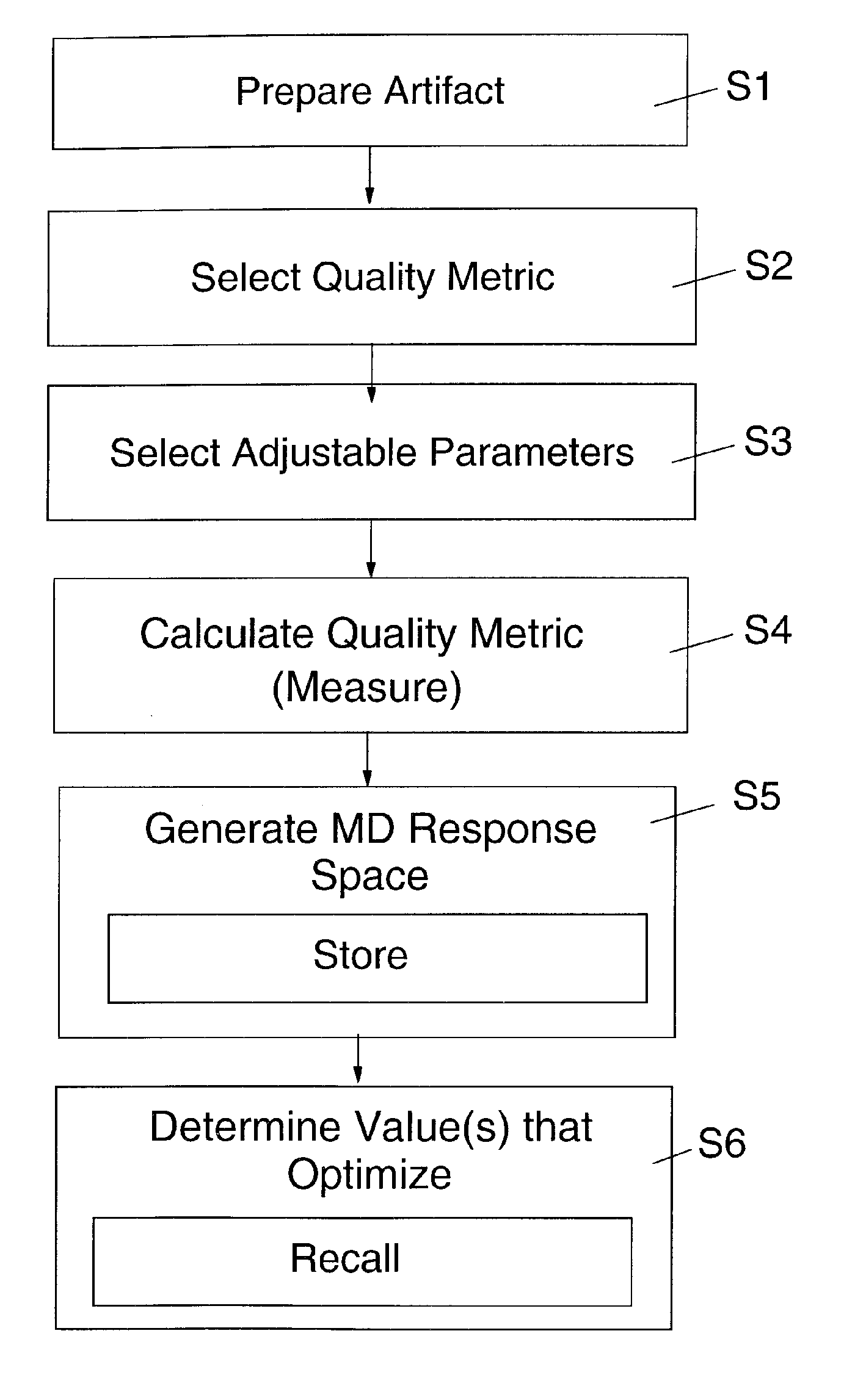
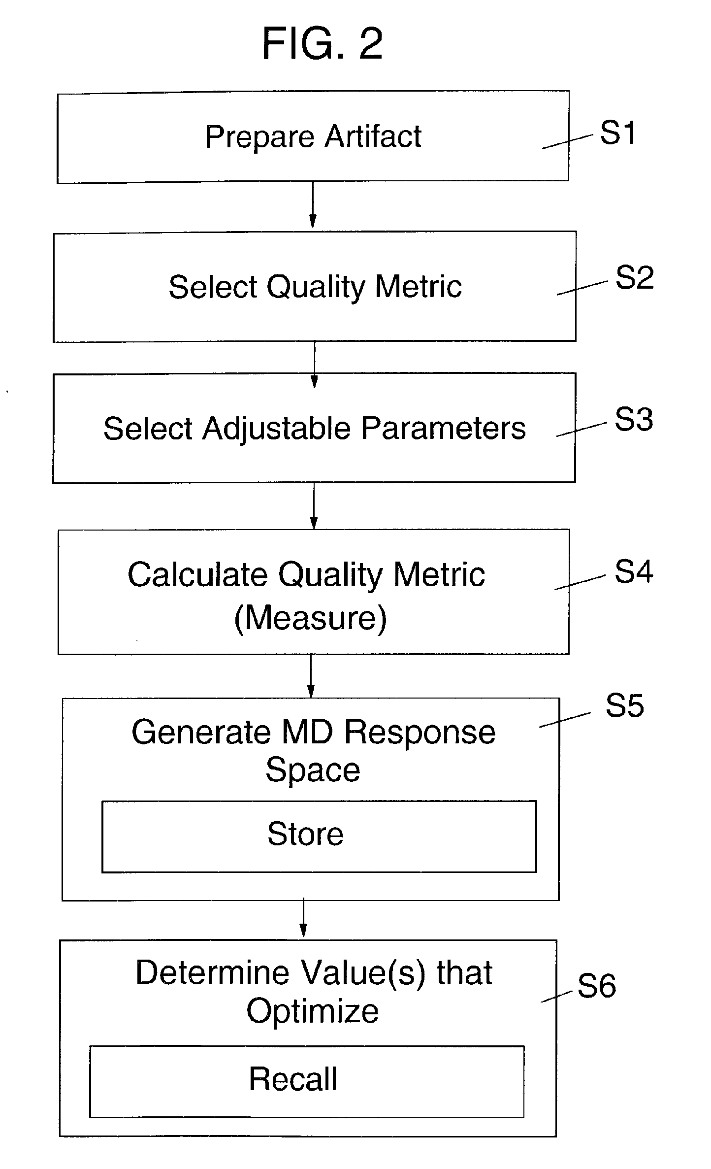
Optimizing a measurement system under test (MSUT) is disclosed. In one embodiment, a method includes selecting a first set of adjustable parameters of the MSUT that affect a quality metric for the MSUT, calculating the quality metric over a range of values of each adjustable parameter in the first set of adjustable parameters, generating a first multidimensional response space based on the calculating step, and determining which value of each adjustable parameter optimizes the quality metric based on the first multidimensional response space. The multidimensional response space may be stored for later recall for other optimization exercises.

Description

BACKGROUND OF THE INVENTION [0001] 1. Technical Field [0002] The invention relates generally to measurement systems, and more particularly, to methods, system and program product for optimizing a measurement system under test (MSUT). [0003] 2. Background Art [0004] Measurement systems (i.e., metrology tool(s)) are used to measure many structures during various process steps in the semiconductor fabrication industry. The measurements may include, for example, gate critical dimensions on a critical dimension scanning electron microscope (CD-SEM) or scatterometry tool, gate dielectric thickness on thin film measuring tools, the overlay between gate level and first level print and via measurement in the back end of line (BEOL). The measurements are used to control processing at levels based on the International Technology Roadmap for Semiconductors (ITRS). [0005] One challenge for obtaining quality measurements is managing the hundred or more decisions being made as measurement recipes ...

Claims


Application Information

Patent Timeline
IPC IPC(8): G01R35/00G06F19/00
CPCG01D18/00
Inventor ARCHIE, CHARLES N.BANKE, GEORGE W. JR.SOLECKY, ERIC P.
Owner GOOGLE LLC
Learn More