Model railroad switch actuators

Inactive Publication Date: 2007-08-16
SOCHA LEIALOHA JOHN
View PDF16 Cites 0 Cited by
  • Summary
  • Abstract
  • Description
  • Claims
  • Application Information

AI Technical Summary

Benefits of technology

[0015] A benefit achieved through use of a spring-biased electrical switch is that once the electrical switch lever or slide passes dead neutral, the spring bias urges the lever or slide to the opposite position without further user input. If flexible linkage is incorporated into the actuator, preferably by using a flexible connecting rod, a soft bias at the switch points can be achieved. Moreover, precise calibration of the distal end connecting rod's throw is not needed, as excessive movement of the slide, actuator lever, and / or proximal end of the connecting rod can be “stored” by the elastic memory of the flexible linkage.
[0018] A feature present in many embodiments is a damper. The damper may be located in or on the housing, and preferably engages any one of the moving linkages in the switch actuator, e.g., the slider or the lever. The purpose of the damper is to decrease the speed at which any of the linked components move, thereby establishing slower movement of the switch when the actuator is linked thereto. This slowed movement better emulates the desired scaled speed of the points movement, thus enhancing realism of the switch. This feature is particularly important when a spring-biased electrical switch is used; the damped motion mitigates the “snap” action of the spring-biased electrical switch. The damper may be any visco-elastic element. In addition, the damper may find particular utility in embodiments employing the spring-biased bidirectional linkage; if a single spring is used, with respect to the previously described embodiment, then the damper may take the form of a micro “shock absorber” or other valved fluid body disposed opposite to the spring.
[0019] While any form of suitable linkage from an engineer's station to the switch actuator is acceptable, the slider is particularly suited for receiving translational input. A preferred means for such input is the use of a shielded cable. Such cables have a flexible core surrounded by a jacket. By linking a distal end of the jacket to the housing and a distal end of the core to the slider, movement of the core relative to the jacket at the proximal end results in desired translation of the slider, when suitable cable alignment is used. Those persons skilled in the art will appreciate the myriad mechanical arrangements available for establishing reciprocating translational input, or substantially reciprocating translational input; the objective is to avoid excessive forces not in the vector of slider movement.
[0020] Where it is possible to select the nature of the mechanical input to the switch actuator, certain components may be removed without departing from the invention. For example, the actuator lever can be directly linked to the lever of the electrical toggle switch at one end, and linked to the proximal end of the connecting rod at the other end. By directly linking the engineer's mechanical input to at least one end of the actuator lever, the invention retains its operability and complexity of the actuator is reduced. Naturally, arcuate movement of the lever is to be taken into consideration, but given the rather limited throw of the lever and the ability of a cable linkage from the engineer's station to the switch actuator to tolerate limited arcuate movement of the distal end of the core, such an arrangement is wholly acceptable. If a different linkage is contemplated, it can be constructed to provide the desired travel geometry to match or substantially match the travel geometry of the actuator lever. Similarly, the slider may function as the sole linkage between the electrical switch and the proximal end of the connecting rod.

Problems solved by technology

To this end, simple solenoid operated switches are not favored; their movement is proportionately too rapid and do not emulate the relatively slow and steady movement of real railroad switches.
Prior efforts to emulate realistic points movement have employed wired switches using stall motors, such as those sold by Circuitron under the brand name “Tortoise.” However, these switches require a source of electric power, an electrical switch and related wiring.
Moreover, control over the relative speed of the switch is generally not possible, thus relegating the hobbyist to the switch speed selected by the manufacturer.

Method used


Image

  • Model railroad switch actuators
  • Model railroad switch actuators
  • Model railroad switch actuators

Examples


Embodiment Construction

[0034] The following discussion is presented to enable a person skilled in the art to make and use the embodiments of the invention. Various modifications to the embodiments will be readily apparent to those skilled in the art, and the generic principles herein may be applied to other embodiments and applications without departing from the spirit and scope of the present invention as defined by the appended claims. Thus, the present invention is not intended to be limited to the embodiments show, but is to be accorded the widest scope consistent with the principles and features disclosed herein.

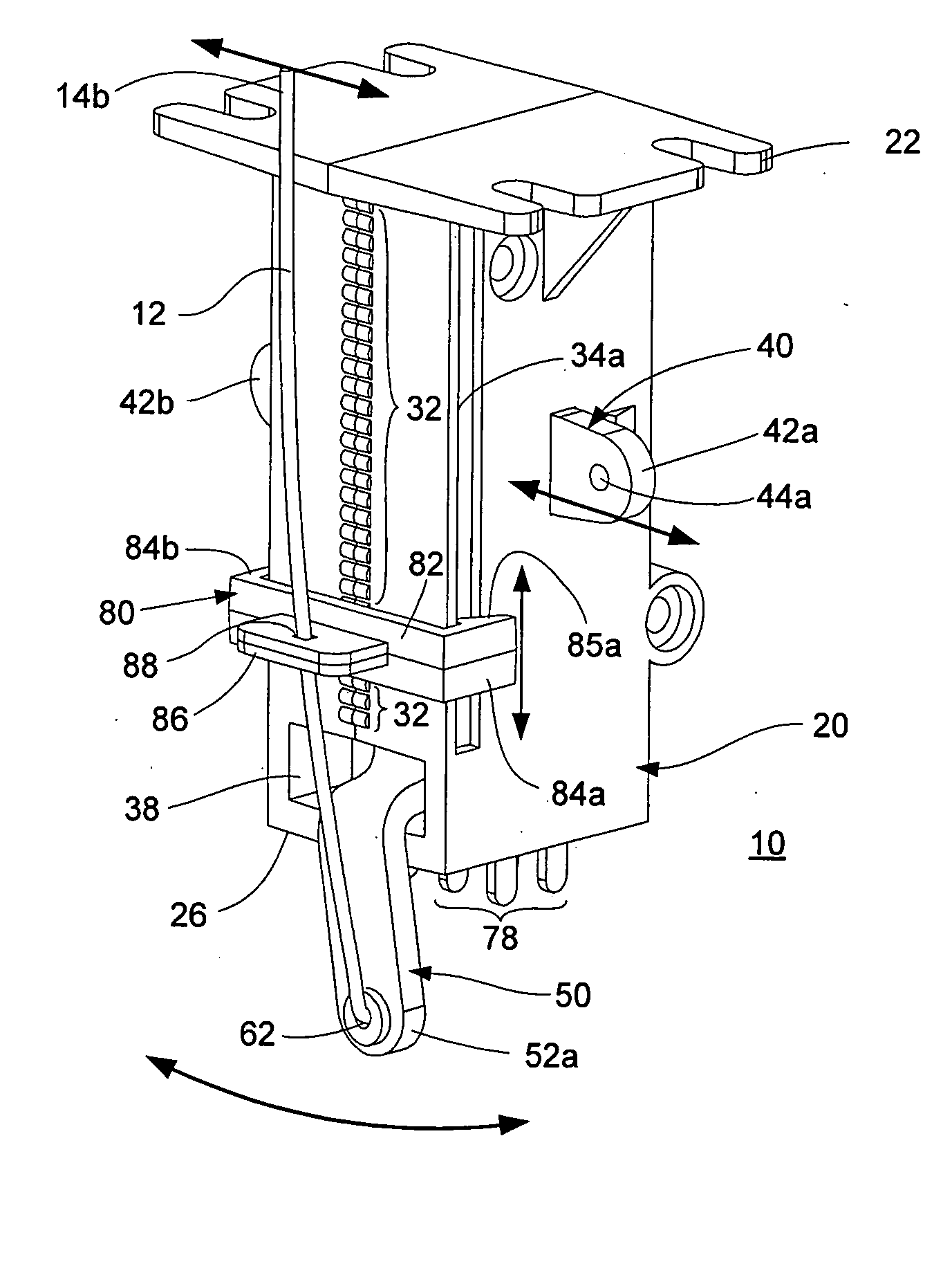
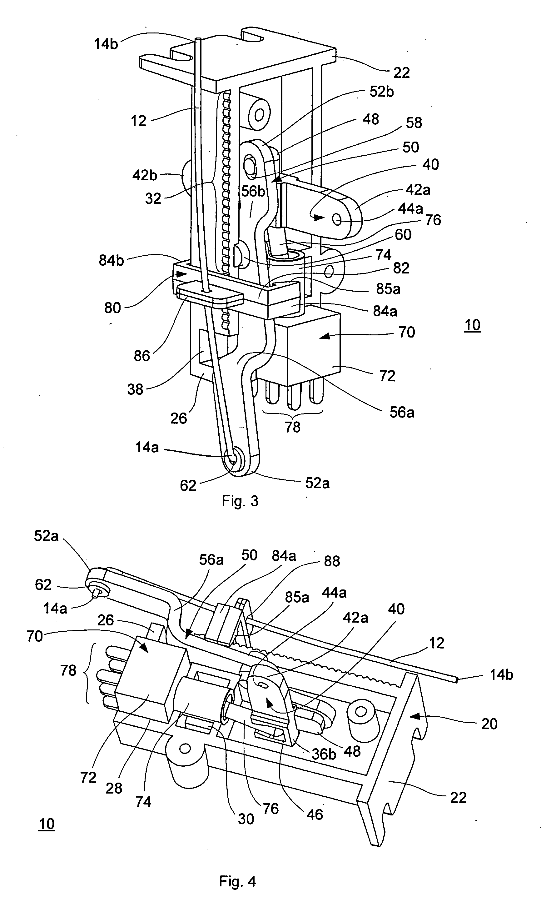
[0035] Turning then to the several Figures wherein like numerals indicate like parts and more particularly to FIGS. 1-4, a first switch actuator 10 is shown. Switch actuator 10 comprises housing 20 slider 40 lever 50 switch 70 and fulcrum 80. In particular, housing 20 includes mounting base 22 switch end 26, detents 32 fulcrum slots 34a and 34b, slider slots 36a and 36b, and lever arm slot 3...


PUM


Abstract

Please amend the application to include the following Abstract of the Invention: A remotely operable switch actuator for model train having a housing adapted to receive an electrical switch having a toggle, a slider translationally received by the housing and linked to the toggle, and a fulcrum for receiving mid portion of a connecting rod. The fulcrum may be translationally received by the housing, which when moved, alters the throw of the connecting rod. In certain embodiments of the invention, the slider has means for receiving a first end portion of the connecting rod where the second end of the connecting rod may engage a throw bar. In other embodiments, the actuator further includes a lever pivotally received by the housing, and linked at one end to the slider and the other end linkable to the connecting rod at one end thereof.

Description

BACKGROUND OF THE INVENTION [0001] 1. Description of the Prior Art [0002] In the field of model railroading, track layouts usually comprise one or more mainlines and one or more sidings. As in conventional railroad lines, sidings are often used for stationary locomotives and cars; for adding, subtracting or substituting locomotives or cars such as in a makeup, or for bypasses; and can be found in crossovers, double ended sidings, lapped sidings, single ended sidings, ladders, wyes, etc. Switches are used in these arrangements for redirecting locomotives and / or cars from a mainline to a siding or for bypassing on a siding. [0003] While there are many forms of switches, each switch generally includes the following components: [0004] Points are the movable rails that guide the wheels towards one diverging track or the other. They generally have tapered ends. [0005] A frog refers to structure at the crossing point of two rails. This can be assembled out of several appropriately cut and ...

Claims


Application Information

Patent Timeline
IPC IPC(8): H01H19/00
CPCH01H23/148H01H15/22
Inventor SOCHA-LEIALOHA, JOHN
Owner SOCHA LEIALOHA JOHN
Why Eureka
Try Eureka