Method of machining work in numerically controlled lathe

Active Publication Date: 2007-08-16
CITIZEN WATCH CO LTD
View PDF4 Cites 11 Cited by
  • Summary
  • Abstract
  • Description
  • Claims
  • Application Information

AI Technical Summary

Benefits of technology

[0017] Furthermore, in this type of NC lathe, the tool rests are moved back and forth between the standby position and the work at a fast feed speed, and there is a problem that if the tool rest is moved at the fast feed speed, a heavy load is repeatedly exerted on a feed mechanism of the tool rest, resulting in a shortened lives of shafts of screws and the like constituting the feed mechanism.
[0027] Furthermore, the time for moving the tool rest at the fast feed speed can be reduced to reduce the load exerted on the feed mechanism, thereby prolonging the life of the feed mechanism.

Problems solved by technology

Furthermore, in this type of NC lathe, the tool rests are moved back and forth between the standby position and the work at a fast feed speed, and there is a problem that if the tool rest is moved at the fast feed speed, a heavy load is repeatedly exerted on a feed mechanism of the tool rest, resulting in a shortened lives of shafts of screws and the like constituting the feed mechanism.

Method used


Image

  • Method of machining work in numerically controlled lathe
  • Method of machining work in numerically controlled lathe
  • Method of machining work in numerically controlled lathe

Examples


first embodiment

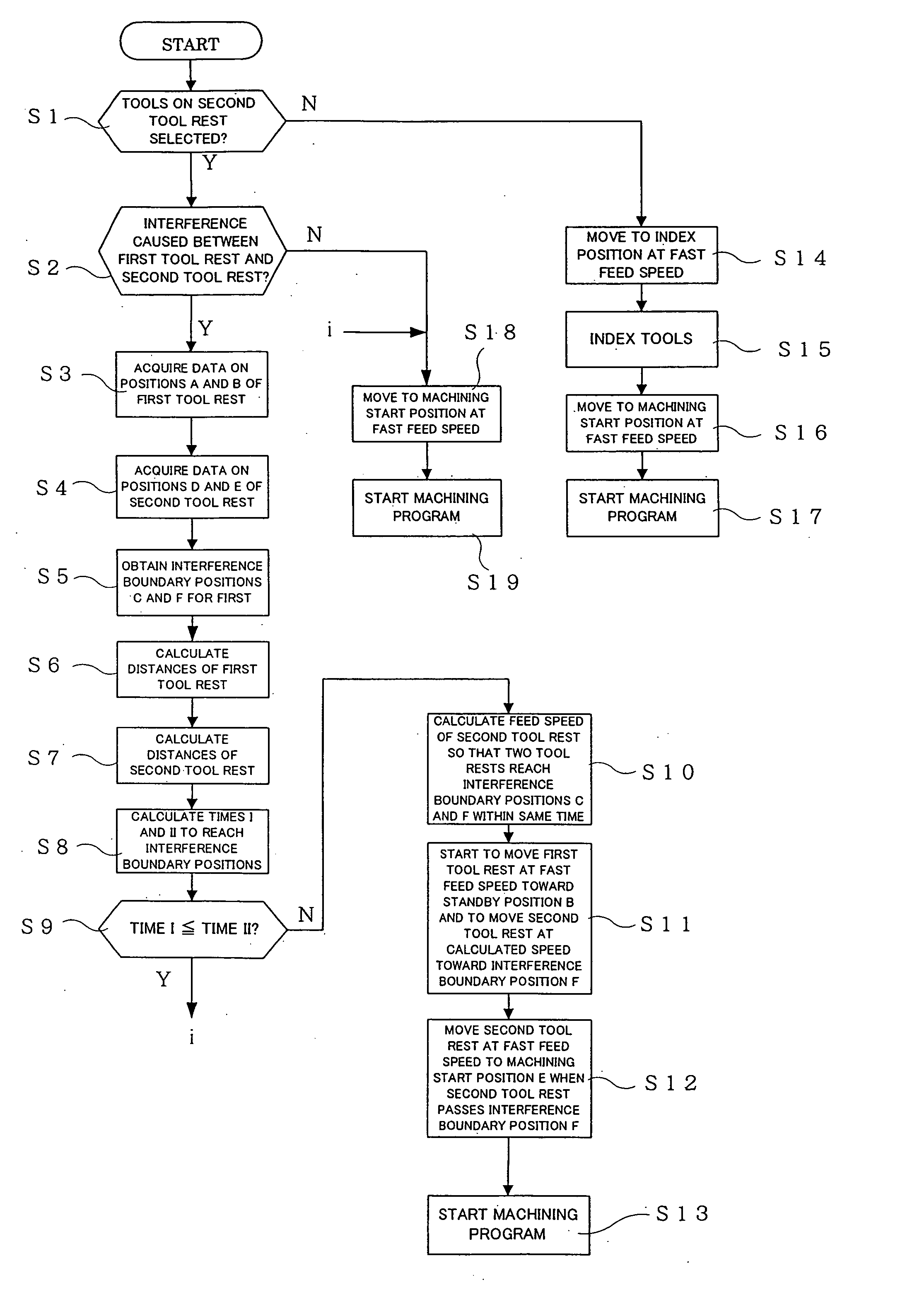
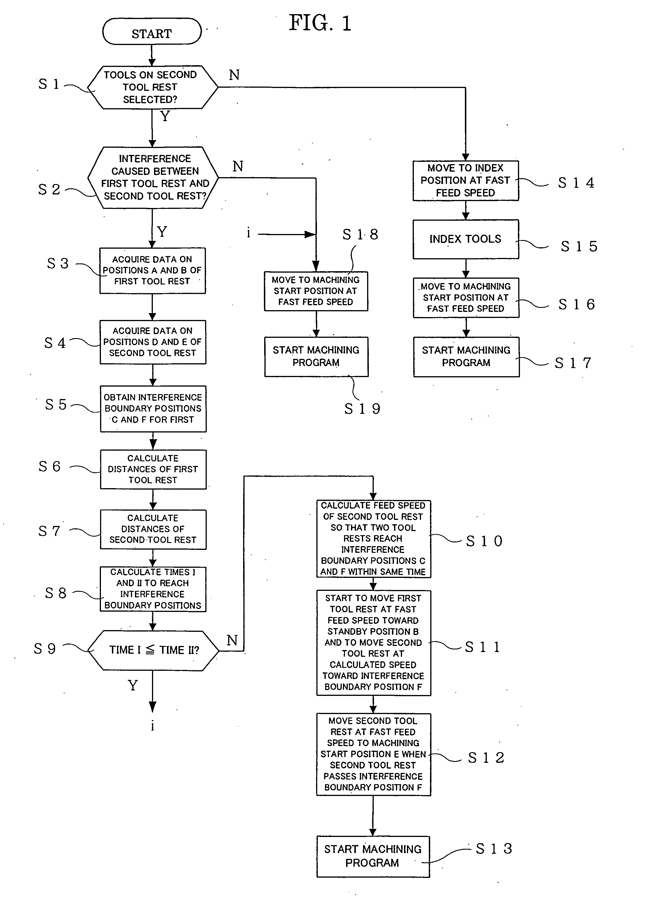
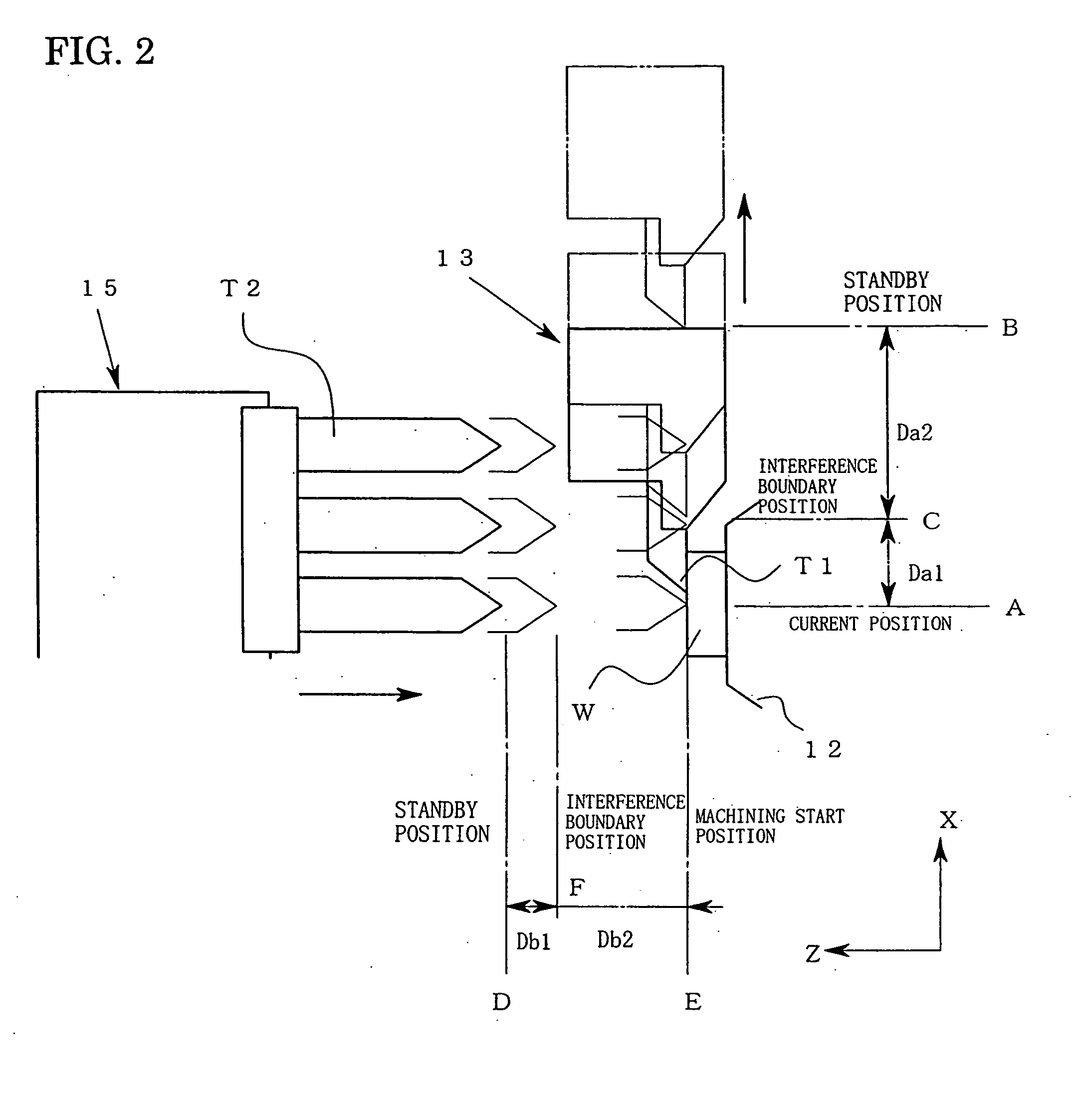
[0038]FIG. 1 is a flowchart explaining a tool switching procedure according to a first embodiment of the present invention. FIG. 2 is a diagram explaining the positional relation between two tool rests in this embodiment. FIG. 3 is a diagram explaining one approach for interference judgment in this embodiment. FIGS. 4 are diagrams showing the positional relation between the first and second tool rests at stages when the machining with tools of the first tool rest is terminated, when both of the tool rests have reached interference boundary positions, and when tools of the second tool rest have reached a machining start position.

[0039] It is to be noted that a NC lathe in this embodiment has the same basic configuration as that of a NC lathe shown in FIGS. 8 and 9, and the same parts and members as those in FIGS. 8 and 9 are given the same numerals and are not described in detail.

[0040] Before starting the machining of a work W, a standby position B for a first tool rest 13 and a s...

second embodiment

[0067] Next, a second embodiment will be described referring to a flowchart of FIG. 6 and to FIG. 7 wherein a plurality of (four in the example shown in the drawing) tools installed on a second tool rest 15 are tools T21 to T24 of different lengths.

[0068] It is to be noted that this embodiment is the same as the first embodiment except that a procedure of setting interference boundary positions C and F is different from the procedure described above. Therefore, the procedure of setting the interference boundary positions C and F will be described below in detail, and the same parts as those in the first embodiment are not described. Moreover, for convenience, the following description is given on the assumption that after a work W has been machined with tools T1 of a first tool rest 13, the tool T24 installed on a lowermost step, among the tools T21 to T24 of the second tool rest 15, is selected as a next machining tool.

[0069]FIG. 6 is a flowchart explaining the procedure of setti...


PUM

PropertyMeasurementUnit
Diameteraaaaaaaaaa
Speedaaaaaaaaaa

Abstract

A method of machining a work in a numerically controlled lathe is provided which is capable of reducing the machining cost by shortening idle time at the time of switching and which is capable of enhancing the lifetime by lessening a load on a feeding mechanism of a tool rest. After completion of the machining of a work W with a tool T1 on one tool rest (13), the one tool rest (13) is moved to a standby position B and, at the same time, the other tool rest (15) is moved from a standby position D and the feed speed of the other tool rest (15) is controlled such that the one and the other tool rests (13, 15) simultaneously reach positions C and F preset between the work W and the standby positions B and D.

Description

TECHNICAL FIELD [0001] The present invention relates to a method of machining a work in a numerically controlled lathe in which the work gripped by a chuck of a rotatable spindle is machined with tools installed on a plurality of tool rests. BACKGROUND ART [0002] A numerically controlled lathe (hereinafter written as a NC lathe) has been known which machines a work gripped by a chuck of a rotatable spindle while switching tools installed on a plurality of tool rests. [0003] One such NC lathe has a first tool rest moving back and forth in an axis line direction traversing the axis line of the spindle, and a second tool rest provided opposite to the spindle and moving back and forth on the axis line of the spindle, wherein the outer peripheral surface of the work is mainly machined with tools installed on the first tool rest, while the end face of the work is mainly machined with tools installed on the second tool rest. [0004]FIG. 8 shows one example of the NC lathe described above, w...

Claims


Application Information

Patent Timeline
IPC IPC(8): B23B3/00B23B1/00B23Q15/00B23Q39/02G05B19/19G05B19/416
CPCB23B1/00B23Q39/027G05B19/416G05B2219/43199Y10T82/2502B23Q2039/008Y10T82/10Y10T82/2524G05B2219/50008
Inventor SHIBUI, YUTAKAMATSUMARU, HAJIMEKAZUIE, KEITA
Owner CITIZEN WATCH CO LTD
Why Eureka
Try Eureka