
Object separating apparatus using gas

a technology of separating apparatus and gas, which is applied in the direction of mechanical equipment, fluid couplings, couplings, etc., can solve the problems of space efficiency degradation and the degradation of the reliability of the entire system, and achieve the effect of simple construction

Active Publication Date: 2007-08-16
AGENCY FOR DEFENSE DEV
View PDF2 Cites 8 Cited by
  • Summary
  • Abstract
  • Description
  • Claims
  • Application Information

AI Technical Summary

Benefits of technology

[0008] Therefore, an object of the present invention is to provide an object separating apparatus using gas in which two objects coupled to each other can be separated from each other and then spaced from each other by a certain safety distance using a simple construction.
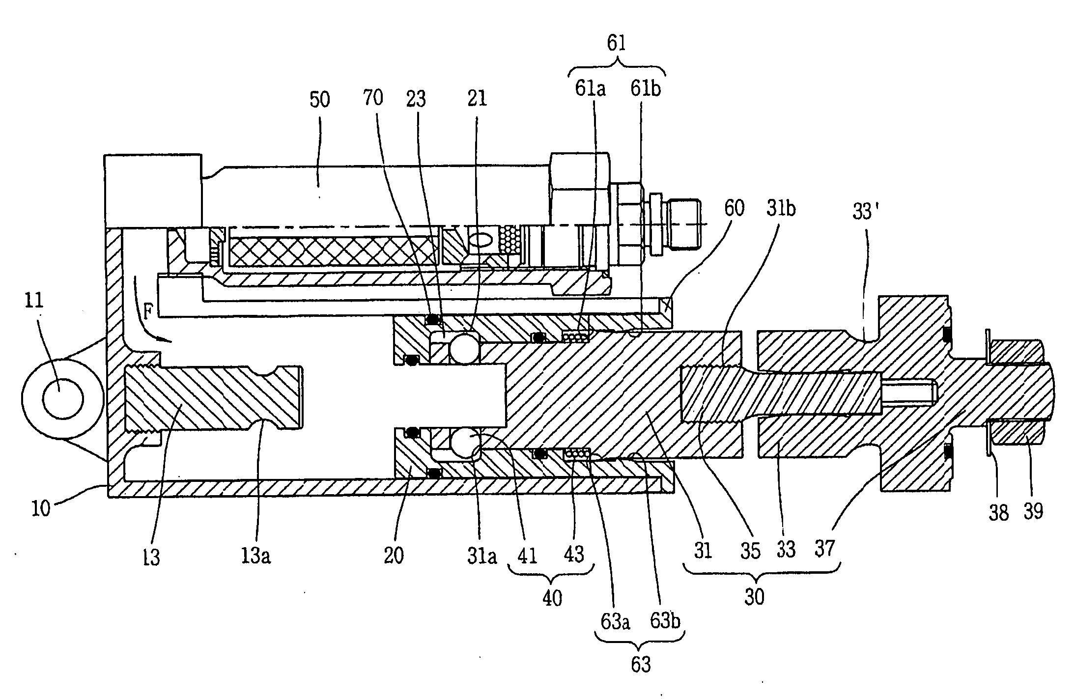
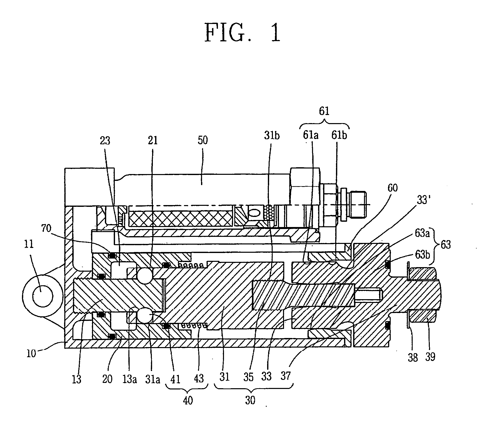
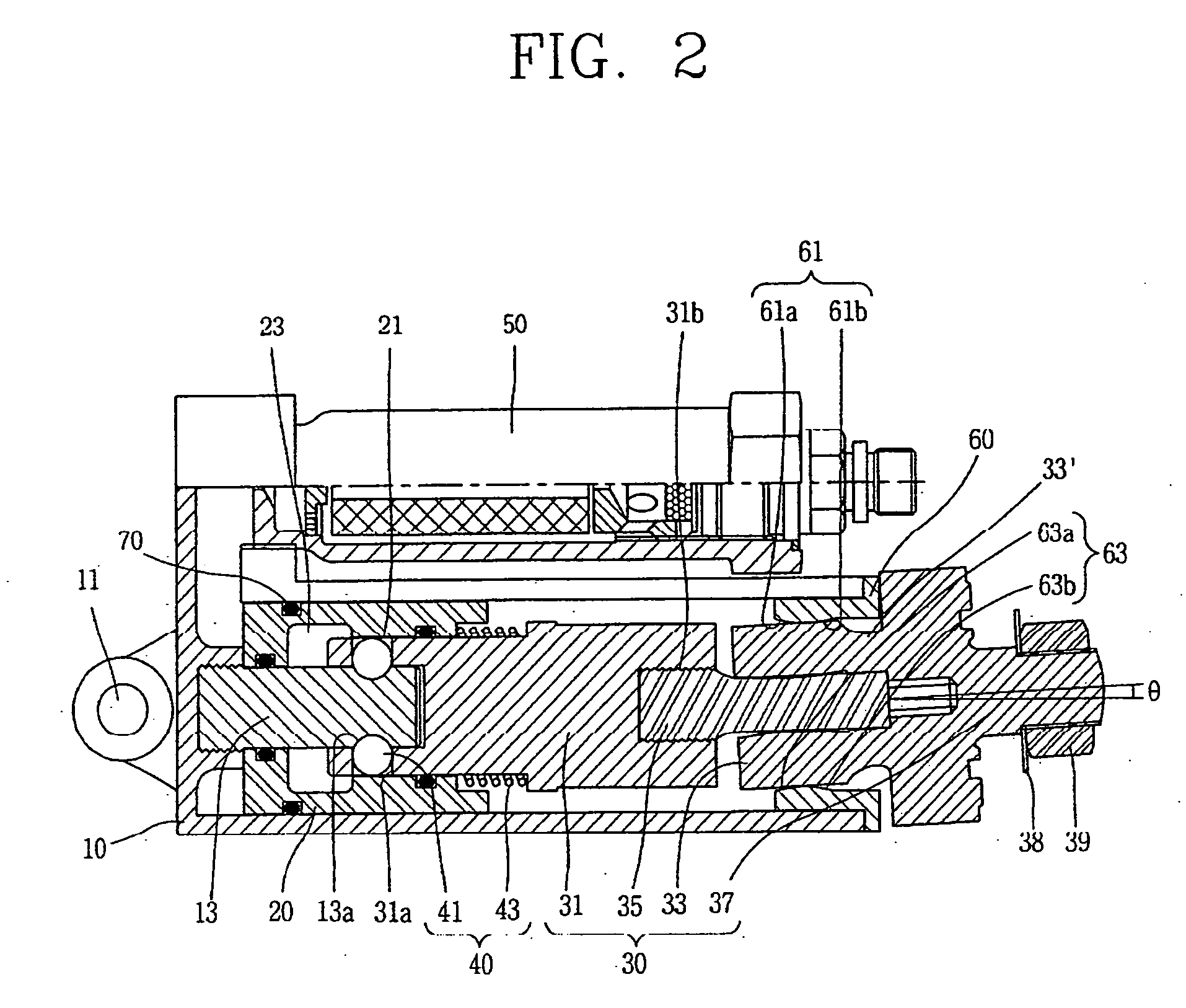
[0010] The housing has a hollow shape. One end of the housing is opened and its closed end is connected to a first object. The cylinder is movably installed at an inner space of the housing in an axial direction of the housing. The piston assembly is connected to the cylinder at the inner space of the housing, and an end thereof which is exposed to the outside of the housing is connected to a second object. The fixing portion fixes the cylinder and the piston assembly into the housing to thus maintain the coupled state between the first object and the second object. The fixing portion includes a plurality of stopping balls disposed in a plurality of receiving holes of the piston assembly so as to be inserted into a ball groove formed at a support portion of the housing, and an elastic body disposed between the piston assembly and the cylinder to pressurize the cylinder into which the inner end of the piston assembly is inserted toward the closed end of the housing to thus prevent the stopping balls from being separated from the ball groove. In addition, as a space portion having an inner diameter greater than that of the pressurizing portion is formed at an inner circumference of the cylinder, when the gas generator is operated to thus push the cylinder toward the piston assembly, the plurality of stopping balls are moved to the space portion. Accordingly, the plurality of stopping balls are fixed into the ball groove to thus release the fixed state of the piston assembly, thereby separating the cylinder and the piston assembly from the housing. The first object connected to the housing is thus separated from the second object connected to the piston assembly. In this way, a simple construction is used to certainly separate one of the first and second objects from the other.

Problems solved by technology

However, in order to use a pressure of the gas generator, a certain sealing space is necessary and thus a space efficiency is degraded.
In addition, in order to operate both the gas generator and the explosive bolt, each power source line therefor has to be designed, and accordingly an entire system becomes complicated, resulting in a degradation of reliability of the entire system.

Method used


Image

  • Object separating apparatus using gas
  • Object separating apparatus using gas
  • Object separating apparatus using gas

Examples


Embodiment Construction

[0022] Description will now be given in detail of the present invention, with reference to the accompanying drawings.

[0023]FIG. 1 is a sectional view illustrating an object separating apparatus using gas in accordance with an embodiment of the present invention.

[0024] As illustrated in FIG. 1, an object separating apparatus using gas in accordance with an embodiment of the present invention includes a housing 10, a cylinder 20, a piston assembly 30, a fixing portion 40 and a gas generator 50.

[0025] The housing 10 has a hollow shape extending toward a longitudinal direction. One end of the housing 10 is closed and the other end is opened. A coupling portion 11 is formed at the closed end, and a first object (not shown) is connected to the housing 10 via the coupling portion 11. A support portion 13 is integrally formed with the closed end or coupled thereto, wherein the support portion 13 has a circular section and protrudes toward an inner space of the housing 10. A ball groove 1...


PUM


Abstract

An object separating apparatus using gas comprising a hollow housing of which closed end is connected to a first object and the other end is opened, a cylinder movably installed at an inner space of the housing in an axial direction of the housing, a piston assembly coupled to the cylinder at the inner space and connected to a second object at an outer end thereof where is exposed to the outside of the housing, a fixing portion disposed between the housing and the cylinder and the piston assembly to fix the cylinder and the piston assembly into the housing, and a gas generator mounted in the housing to be communicated with the inner space, wherein when the gas generator is operated, the gas generator pressurizes the cylinder to thus release the fixed state between the cylinder and the piston assembly by the fixing portion and simultaneously to separate the cylinder and the piston assembly from the housing, whereby a simple construction can be achieved and the first and second objects can effectively be separated and spaced from each other.

Description

BACKGROUND OF THE INVENTION [0001] 1. Field of the Invention [0002] The present invention relates to an object separating apparatus using gas, and particularly, to an object separating apparatus using gas for forcibly separating two objects coupled to each other from each other out of a safety distance. [0003] 2. Background of the Invention [0004] In general, a system for separating a guided missile from a launcher platform in land or on ship uses an explosive bolt. Namely, the guided missile is connected (e.g., restricted) to the launcher platform by the explosive bolt, and is instantaneously separated from the launcher platform. The explosive bolt connects and disconnects two objects coupled to each other. In a guided weapon system, the explosive bolt is used in order to simply separate the guided missile from the launcher platform. The guided missile separated from the launcher platform is forcibly moved to a certain safety distance by a thrust of a propellant. [0005] Since the e...

Claims


Application Information

Patent Timeline
IPC IPC(8): F16D31/02
CPCF15B15/19E04G21/3204E04G11/20
Inventor KIM, HEUNG-YOULJUN, YONG-BUMKIM, SANG-HWA
Owner AGENCY FOR DEFENSE DEV
Learn More