
Wall frame hanging apparatus

a technology for hanging apparatuses and wall frames, which is applied in the direction of hinges, machine supports, manufacturing tools, etc., can solve the problems of difficult to ensure that difficult for the user to “find”, and the user is usually unable to see whether the frame is correctly mounted on the fastener. , to achieve the effect of facilitating the rotation of the hanger, reducing the movement of the hanger, and large surface area

Inactive Publication Date: 2007-08-16
WILTON INDS
View PDF6 Cites 23 Cited by
  • Summary
  • Abstract
  • Description
  • Claims
  • Application Information

AI Technical Summary

Benefits of technology

[0008] The lips require the hanger to be lifted off of the plate, and reduce movement of the hanger away from the wall. The contacting substantially circular cylindrical surfaces facilitate rotation of the hanger relative to the plate, in order to adjust the position of the frame, and provide large surface areas to ease mounting of the frame on the wall. A chamfered plate edge adjacent the first lip accommodates a hammer's head, and, due to an angled aperture through the edge, angles the fastener, which can be a nail, into the wall. This angling enhances the holding strength of the fastener.

Problems solved by technology

One disadvantage of conventional structures is that they are difficult for the user to “find” when the back of the frame faces away from the user.
Because one cannot see the nail and the hanging structure mounted on the back of the frame when the frame is being hung on the wall, it is difficult to ensure that engagement has occurred.
Even after hanging, one cannot usually see whether the frame is correctly mounted on the fastener.
If the user assumes that engagement has taken place when it has not, the frame may later drop and break.
Another disadvantage with conventional frame-hanging structures is that the frames often are not level after hanging.
This can take place due to incorrect placement of the frame on the fastener, or due to movement of the frame after correct placement.

Method used


Image

  • Wall frame hanging apparatus
  • Wall frame hanging apparatus
  • Wall frame hanging apparatus

Examples


Embodiment Construction

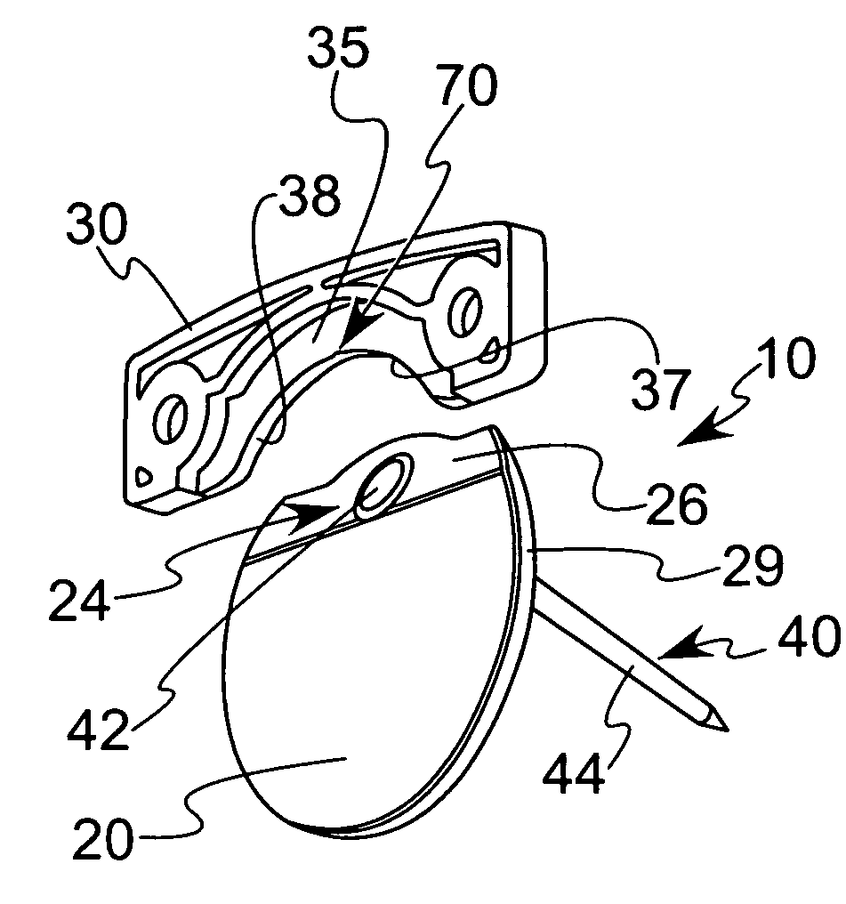
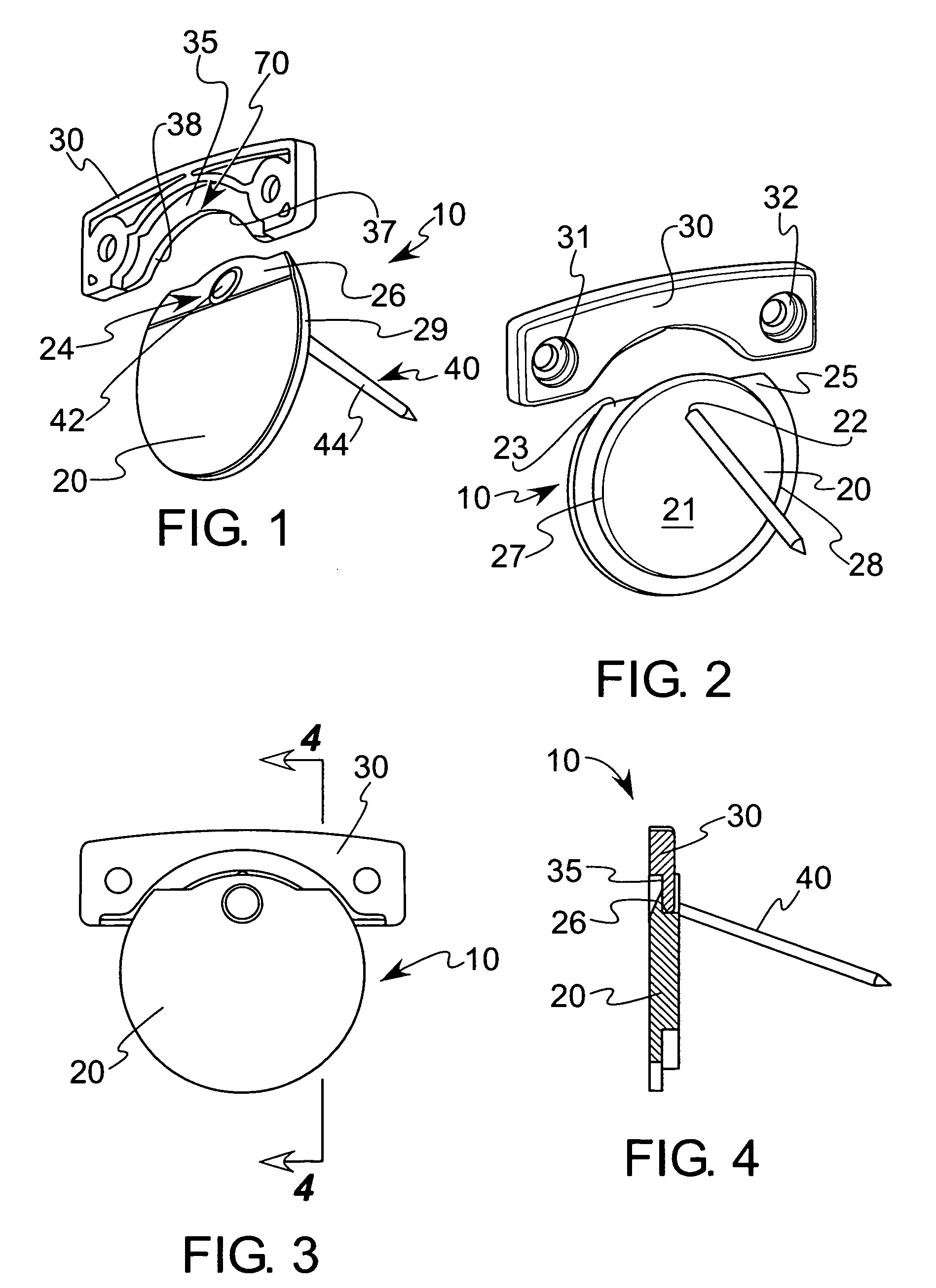
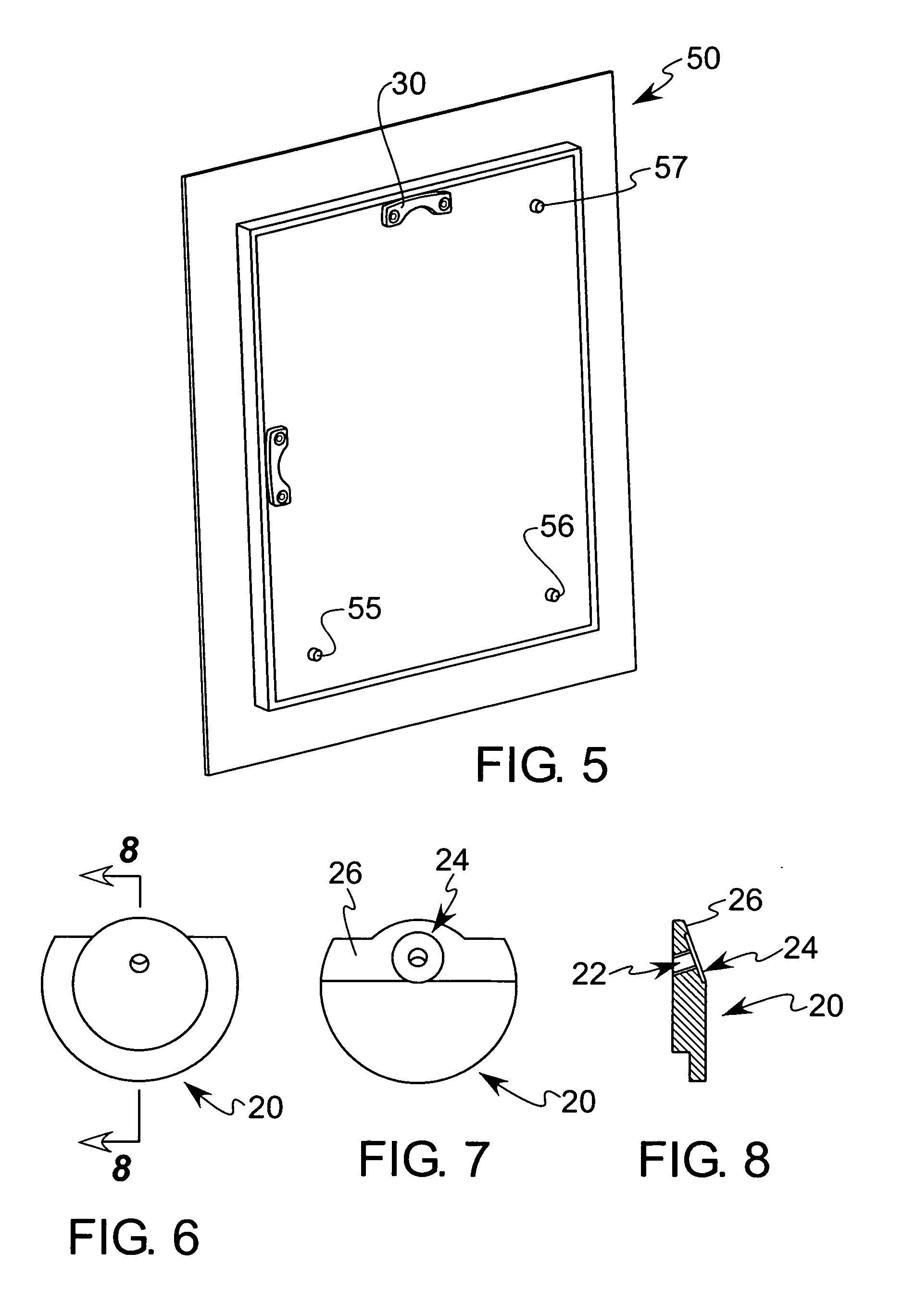
[0058] The preferred embodiment of the present invention is illustrated in FIG. 1, which shows the hanging apparatus 10 having a plate 20, a hanger 30 and a fastener, such as the nail 40. The plate 20 is preferably a flat sheet of relatively strong material, such as plastic, metal, wood or a composite material, and has an aperture 22 near its upper edge, as shown in FIGS. 1 and 2. The nail 40 has a shaft 44 that extends through the aperture 22 and into a wall, as described further below. The nail head 42 seats in a recess 24 formed on one side of the aperture 22, causing the top of the nail head to lie essentially flush with, or slightly above, the plane of the surface in which the aperture 22 is formed.

[0059] The plate 20 has a chamfered edge 26 formed on its upper end as shown in FIGS. 1, 7 and 8. This edge 26 is angled relative to the parallel, major faces of the plate 20 by approximately 20 degrees, although the angle can vary between a few degrees and almost 90 degrees. The ap...


PUM


Abstract

An apparatus for mounting a hanging frame, such as a picture frame, to a wall. A plate with radially outwardly-facing substantially circular cylindrical surfaces attaches to a wall. A hanger mounts to the frame and has radially inwardly-facing substantially circular cylindrical surfaces seating against the cylindrical surfaces of the plate. The plate has a first lip extending radially outwardly of the cylindrical surfaces of the plate and the hanger has a second lip extending radially outwardly of the cylindrical surfaces of the hanger. The first and second lips seat against one another when the hanger is on the plate for resisting plate movement away from the wall. The lips require the hanger to be lifted off of the plate. The contacting substantially circular cylindrical surfaces facilitate rotation of the hanger relative to the plate.

Description

BACKGROUND OF THE INVENTION [0001] 1. Field of the Invention [0002] This invention relates generally to hangers for wall frames, such as pictures, plaques, easels and other structures that are hung on a wall. [0003] 2. Description of the Related Art [0004] It is common to hang wall frames, such as picture frames, against walls by installing a fastener, such as a nail, screw or pin that penetrates a wall, to the wall, and then hanging the downwardly facing edge of a structure attached to the frame on the fastener. Some structures that are conventionally attached to a frame for hanging on the fastener, such as a common nail, include a wire extending across the frame's back or a bar mounted to the frame's back with a downwardly facing edge having a plurality of “saw tooth” notches and metal loops. Another prior art frame-hanging structure is found in U.S. Pat. No. 6,719,260 to Hart. [0005] One disadvantage of conventional structures is that they are difficult for the user to “find” whe...

Claims


Application Information

Patent Timeline
IPC IPC(8): E05D1/04
CPCY10T16/542A47G1/1613
Inventor BROEHL, JOSHUA MICHAELSTAUFENBERG, DONALD JAMESFLOAT, JAMISON JOSEPH
Owner WILTON INDS
Learn More