
Electronic component package

a technology of electronic components and components, applied in piezoelectric/electrostrictive/magnetostrictive devices, piezoelectric/electrostriction/magnetostriction machines, semiconductor devices, etc., can solve the problems of false operation, difficult to render the case small in thickness, and increase the cost, so as to prevent the melting of sealant and improve the yield of vacuum tight sealing, the effect of favorable detection sensitivity behavior

Inactive Publication Date: 2007-08-09
CITIZEN WATCH CO LTD
View PDF8 Cites 103 Cited by
  • Summary
  • Abstract
  • Description
  • Claims
  • Application Information

AI Technical Summary

Benefits of technology

The patent text describes a problem with sealing electronic components in a case, where the sealant can flow into the case and cause issues with the components. The text proposes a solution by providing a shielding electrode and a ground electrode to create a barrier and prevent the sealant from flowing. The text also discusses the use of a vacuum-tight sealing method to improve the frequency characteristics and stability of the oscillator device. Additionally, the text describes a new manufacturing method that reduces the time it takes for the crystal oscillator to start a stable drive and improves the performance of physical sensors.

Problems solved by technology

However, there are problems that the two-layer structure renders the configuration complicated, and therefore, the cost is increased.
In addition, this configuration makes it difficult to render the case small in thickness.
An IC and high resistor electronic components on the circuit board tend to pick up a noise from the outside, and if an influence is exerted by the noise, it may cause a false operation.
In the electronic component package, a noise may occur from a piezoelectric oscillator piece stored inside the case or the electrode installed on the piezoelectric oscillator at the time of starting up, and it may cause an adverse effect on the IC and the high resistance electronic components on the circuit board that is provided in a product in which the electronic component package is mounted.

Method used


Image

  • Electronic component package
  • Electronic component package
  • Electronic component package

Examples


Embodiment Construction

[0115] Hereinafter, the electronic component package according to the present invention will be explained in detail with reference to the accompanying drawings.

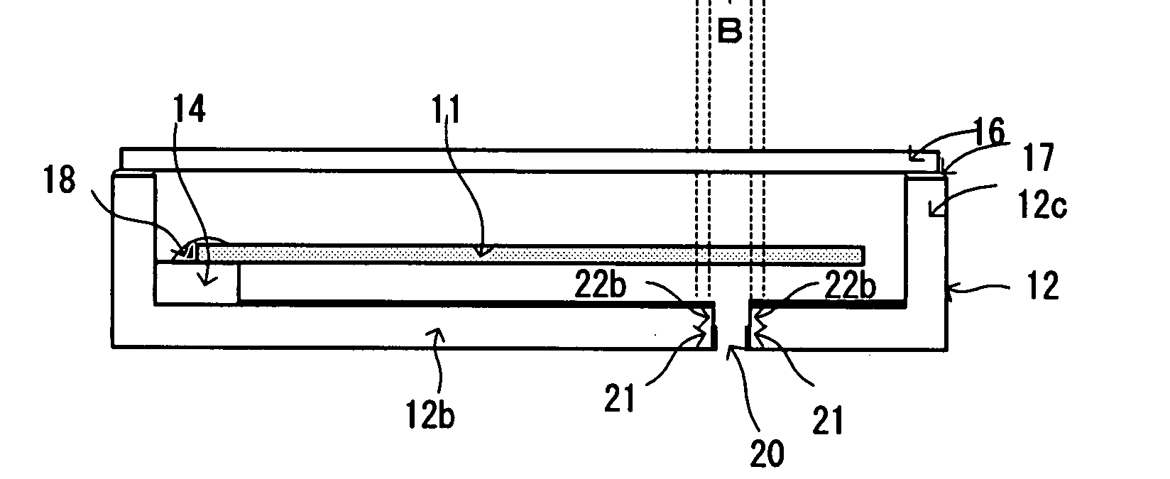
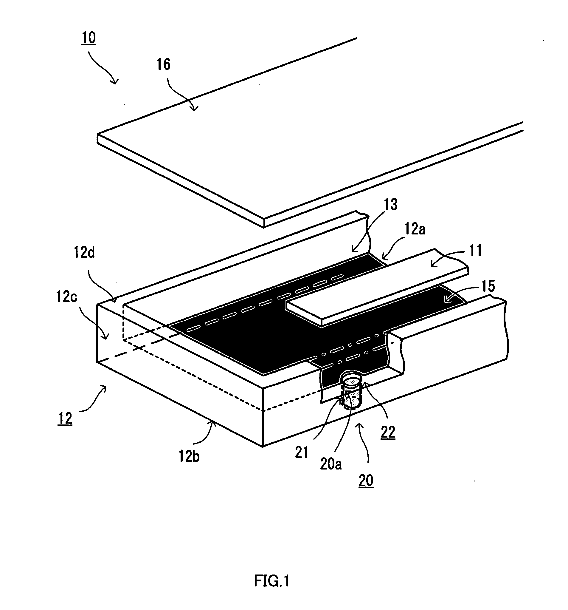
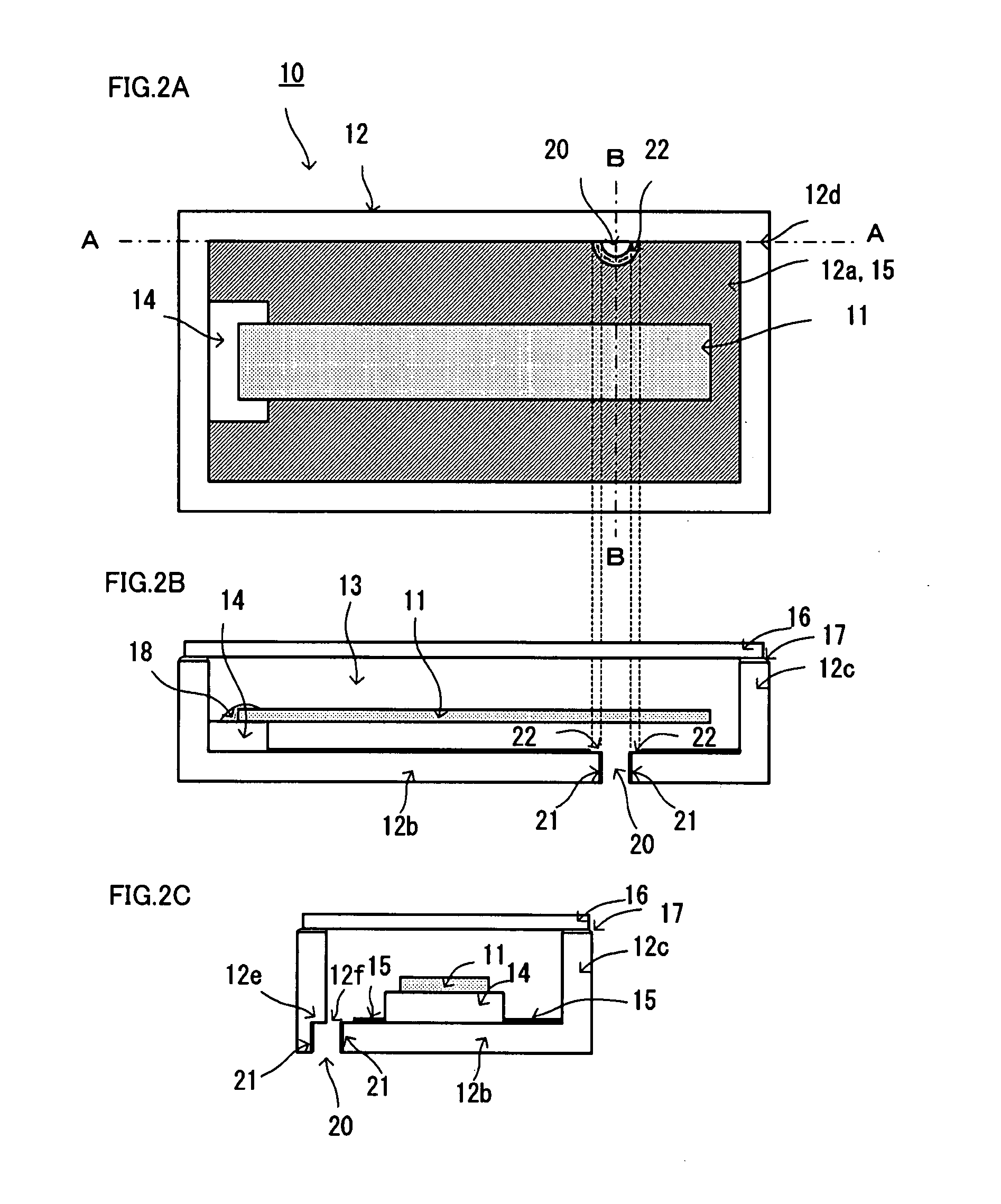
[0116]FIG. 1 illustrates a schematic configuration to explain the electronic component package according to an aspect of the present invention. In FIG. 1, the electronic component package 10 includes a case 12 that has an opening and stores in a storage 13 an electronic component such as a piezoelectric oscillator 11, and a lid 16 that is joined to the rim of the opening to cover the opening.

[0117] The case 12 is provided with an inner surface 12a that supports an edge of the piezoelectric oscillator 11 by a support part 14 (not illustrated in FIG. 1) to store the oscillator, a side wall 12c that surrounds the periphery of the inner surface 12a, and a bottom part 12b that closes the opposite side of the opening end of the side wall 12c. The inner surface 12a and the sidewall 12c forms a space corresponding to the storage pa...


PUM


Abstract

The present invention is to prevent melted sealant from flowing into the interior of a case of an electronic component package that is provided with a shielding electrode on the inner surface of the case, fill a through-hole with the sealant with reliability, and perform vacuum airtight sealing. The electronic component package 10 has a case 12 that has an opening and stores an electronic component (piezoelectric oscillator 11) in the storage inside, and a lid 16 that is joined to the rim of the opening to cover the opening, and airtightly seals a through-hole 20 provided on the bottom part 12b of the case 12 to communicate with the outside, by using a sealant 30. The electronic component package is provided with a shielding electrode 15 on the inner surface of the case to remove a noise influence, and further provided with a configuration to set a part (nonmetal part 22) between the through-hole 20 and the shielding electrode 15, the part being low in wettability with the melted sealant 30, thereby making it difficult to flow the melted sealant 30 from the through-hole 20 into the case 12 along the shielding electrode 15, preventing the melted sealant 30 from flowing into the case 12.

Description

TECHNICAL FIELD [0001] The present invention relates to an electronic component package that is obtained by storing an electronic component such as a piezoelectric oscillator including a crystal oscillator in a case made up of a substrate such as ceramics, and thereafter subjecting the case to airtight sealing with a lid. The present invention further relates to a physical sensor that employs this electronic component package. RELATED ART [0002] An electronic component such as a piezoelectric oscillator device is structured by storing an oscillatory element in such a manner as being airtightly sealed within a package which is made up of a case of an insulating substrate such as ceramics and a metallic lid that seals an opening of the case, for instance. [0003] In accordance with downsizing in dimension and in thickness of an electronic product, there is a growing requirement for the electronic component such as the piezoelectric oscillator device to be further smaller and thinner in...

Claims


Application Information

Patent Timeline
Patent Type & Authority Applications(United States)
IPC IPC(8): H01L41/053H10N30/00H10N30/88
CPCH03H9/1021H01L2924/16315
Inventor KIGAWA, KEISUKESAKURAI, MITSUMASA
Owner CITIZEN WATCH CO LTD
Learn More