
Baffled liner cover

a liner cover and spherical technology, applied in the field of equipment, can solve the problems of low furnace , lower temperature, and ineffective thermal process such as chemical vapor deposition

Active Publication Date: 2007-08-09
HANGZHOU DUNYUANJUXIN SEMICON TECH CO LTD
View PDF14 Cites 205 Cited by
  • Summary
  • Abstract
  • Description
  • Claims
  • Application Information

AI Technical Summary

Benefits of technology

[0007]A broad aspect of the invention includes a cover for a liner used in thermal substrate processing for accommodating a tower supporting multiple substrates in a vertical arrangement. The cover allows a substantial flow of process gas therethrough while blocking most particl

Problems solved by technology

However, the open bottom end of the bell jar 16 and the mechanical support of the pedestal 22 causes the lower end of the furnace 10 to have a lower temperature, often low enough that the thermal process such as chemical vapor deposition is not effective.
However, quartz towers and injectors are being supplanted by silicon towers, liners, and injectors.
Any die on which a particle falls is likely to be inoperable or at least undependable.
That is, particles severely affect yield.

Method used


Image

  • Baffled liner cover
  • Baffled liner cover
  • Baffled liner cover

Examples


Embodiment Construction

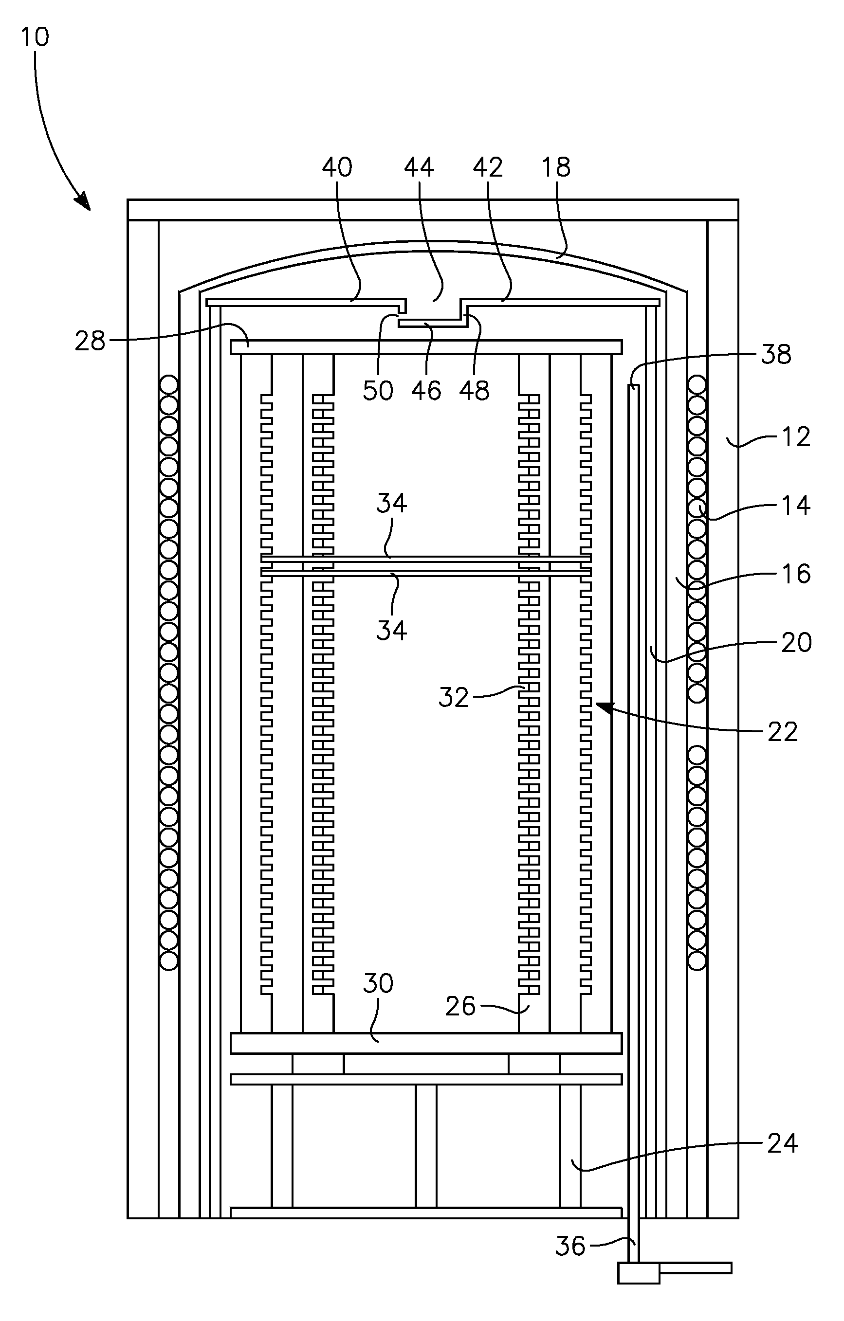
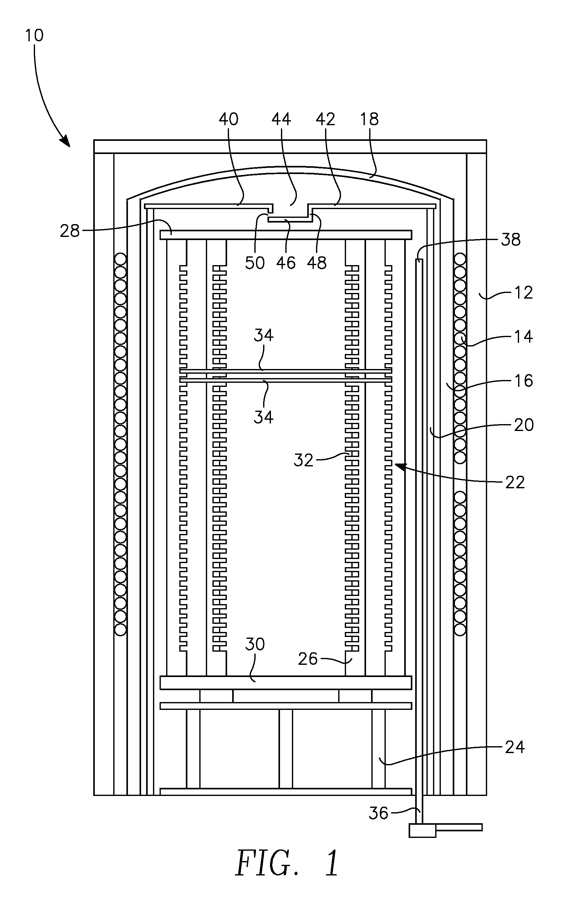
[0015]One aspect of the invention includes, as illustrated in the partially sectioned elevational view of FIG. 1 and which has already been partially described, a cover 40 disposed over the top of the liner 20 that catches falling particles but allows a regular flow of processing gas between the interior of the liner 20 and the top of the furnace. The cover 40 of the embodiment of FIG. 1 includes a generally planar top disk 42 supported on its periphery on the liner 20 and having a large central aperture 44 generally arranged around the central axis of the tower 22 and its supported wafers 34. A horizontally extending floor 46 is suspended from the top disk 42 by sidewalls 48. A plurality of horizontally extending baffle holes 50 penetrate the sidewalls 48 to provide restricted gas flow between the interior of the liner 20 and the exterior.

[0016]The gas injector 34 injects processing gas into the interior of the liner 20 and the unillustrated vacuum pump at the bottom of the apparat...


PUM

PropertyMeasurementUnit
Fractionaaaaaaaaaa
Fractionaaaaaaaaaa
Angleaaaaaaaaaa

Abstract

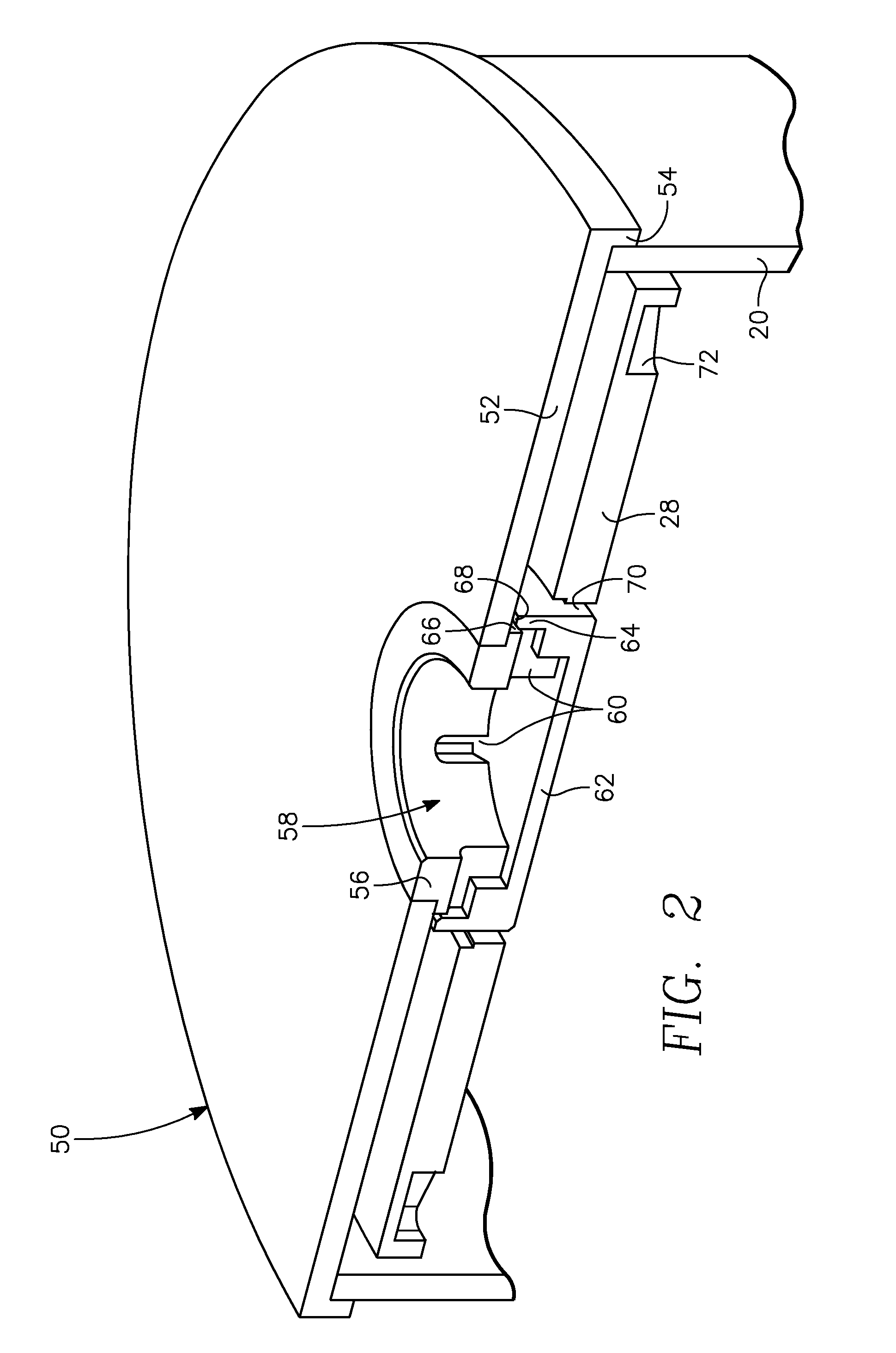
A baffled liner cover supported at the top of a liner surrounding a wafer support tower for semiconductor thermal processing. The cover may present a continuous horizontal surface for preventing particles from falling within the liner but present horizontal extending gas passageways in a baffle assembly to allow the flow of processing gas through the cover. In one embodiment, the baffle assembly includes a cup-shaped member disposed in a central aperture of a top plate having an open top, a continuous bottom, horizontal holes through the sides, and a flange around sides defining a convolute annular passage. Alternatively, the planar top plate may included slanted holes therethrough or vertical holes occupying a small fraction of the surface area. The liner and cover may be composed of quartz, silicon carbide, or preferably silicon.

Description

FIELD OF THE INVENTION[0001]The invention relates generally to equipment used in thermal process of substrates. In particular, the invention relates to a generally tubular liner used for semiconductor processing in a thermal oven.BACKGROUND OF THE INVENTION[0002]Batch thermal processing continues to be used for several stages of fabrication of silicon integrated circuits. One low temperature thermal process deposits a layer of silicon nitride by chemical vapor deposition, typically using chlorosilane and ammonia as the precursor gases at temperatures in the range of about 700° C. Other, high-temperature processes include oxidation, annealing, silicidation, and other processes typically using higher temperatures, for example above 1000° C. or even 1350° C.[0003]For large-scale commercial production, vertical furnaces and vertically arranged wafer towers supporting a large number of wafers in the furnace are typically used, often in a configuration illustrated in the schematic cross-s...

Claims


Application Information

Patent Timeline
IPC IPC(8): C23C16/00
CPCH01L21/67109H01L21/02H01L21/324
Inventor CADWELL, TOM L.SKLYAR, MICHAEL
Owner HANGZHOU DUNYUANJUXIN SEMICON TECH CO LTD
Learn More