
Crystal structure of cytochrome P450 3A4 and uses thereof

a technology of cytochrome p450 and crystal structure, which is applied in the field of crystal structure of cytochrome p450 3a4, can solve the problems of chancy and difficult process of crystallising a protein, major obstacle in the process, and inability to achieve clear and objective results

Inactive Publication Date: 2007-08-02
ASTEX THERAPEUTICS LTD
View PDF17 Cites 5 Cited by
  • Summary
  • Abstract
  • Description
  • Claims
  • Application Information

AI Technical Summary

Benefits of technology

[0100] As explained herein below, the coordinates of the structures of the present invention may be varied within certain root mean square deviations (rmsd) of the structures provided. Since rmsd is a positive value, the term “±a root mean square deviatio...

Problems solved by technology

Another level of complication results from the fact that these enzymes exhibit different tissue distributions and polymorphisms between individuals and ethnic populations
One of the greatest problems in drug discovery is the prediction of the role of cytochrome P450s on the metabolism or modification of drug leads.
These interactions can have serious clinical consequences.
It is well-known in the art of protein chemistry, that crystallising a protein is a chancy and difficult process without any clear expectation of success.
It is commonly held that crystallization of protein molecules from solution is the major obstacle in the process of determining protein structures.
The reasons for this are many; proteins are complex molecules, and the delicate balance involving specific and non-specific interactions with other protein molecules and small molecules in solution, is difficult to predict.
Simply supersaturating the protein to bring it out of solution may not work, the result would, in most cases, be an amorphous precipitate.
Many kits are available (e.g. from Hampton Research), which attempt to cover as many parameters in crystallization space as possible, but in many cases these are just a starting point to optimise crystalline precipitates and crystals which are unsuitable for diffraction analysis.
Even so, crystallization of proteins is often regarded as a time-consuming process, whereby subsequent experiments build on observations of past trials.
In cases where protein crystals are obtained, these are not necessarily always suitable for diffraction analysis; they may be limited in resolution, and it may subsequently be difficult to improve them to the point at which they will diffract to the resolution required for analysis.
It may be due to intrinsic mobility of the protein within the crystal, which can be difficult to overcome, even with other crystal forms.
It may be due to high solvent content within the crystal, which consequently results in weak scattering.
Alternatively, it could be due to defects within the crystal lattice which mean that the diffracted x-rays will not be completely in phase from unit to unit within the lattice.
Any one of these or a combination of these could mean that the crystals are not suitable for structure determination.
It is often hard to predict how a protein could be re-engineered in such a manner as to improve crystallisability.
Our understanding of crystallisation mechanisms are still incomplete and the factors of protein structure which are involved in crystallisation are poorly understood.
Current technologies for generating x-rays and recording diffraction data lead to loss of all phase information.
This “phase information” must be in some way recovered and the loss of this information represents the “crystallographic phase problem”.
The process of model building and fitting the amino acids to the electron density can be both a time consuming and laborious process.

Method used


Image

  • Crystal structure of cytochrome P450 3A4 and uses thereof
  • Crystal structure of cytochrome P450 3A4 and uses thereof
  • Crystal structure of cytochrome P450 3A4 and uses thereof

Examples


examples

Cloning of 3A4

[0413] 3A4 corresponding to M18907 (GI—181373) was cloned from human liver library (Origene Technologies, Inc.).

[0414] PCR carried out as recommended by the manufacturer:

Liver library 2.0 μl10× PCR buffer (−Mg2+) 2.5 μl10 mM dNTPs 0.5 μl10 mM MgSO4 2.5 μlWater11.0 μlPrimer 1 (@ 10 pmol / μl) 3.0 μlPrimer 2 (@ 10 pmol / μl) 3.0 μl

[0415] Primer 1 is complementary to the 5′ end of the full length 3A4 cDNA. Primer 2 is complementary to the 3′ end of the cDNA and adds a four histidine tag onto the C-terminus of the 3A4 protein.

[0416] Heat to 94° C., add 0.5 μl (1 Unit) Vent polymerase

[0417] 35 cycles as follows:

94° C.30 seconds65° C.60 seconds72° C.60 seconds

[0418] Following the addition of 1 μl (2.5 Units) Taq polymerase and incubation at 72° C. for 10 minutes, 1 μl of product was used in a TOPO cloning reaction (vector pCR4TOPO, Invitrogen). The cloning reaction was used to transform E. coli XL1-blue and positive clones identified by NdeI / SalI restriction digestion o...


PUM


Abstract

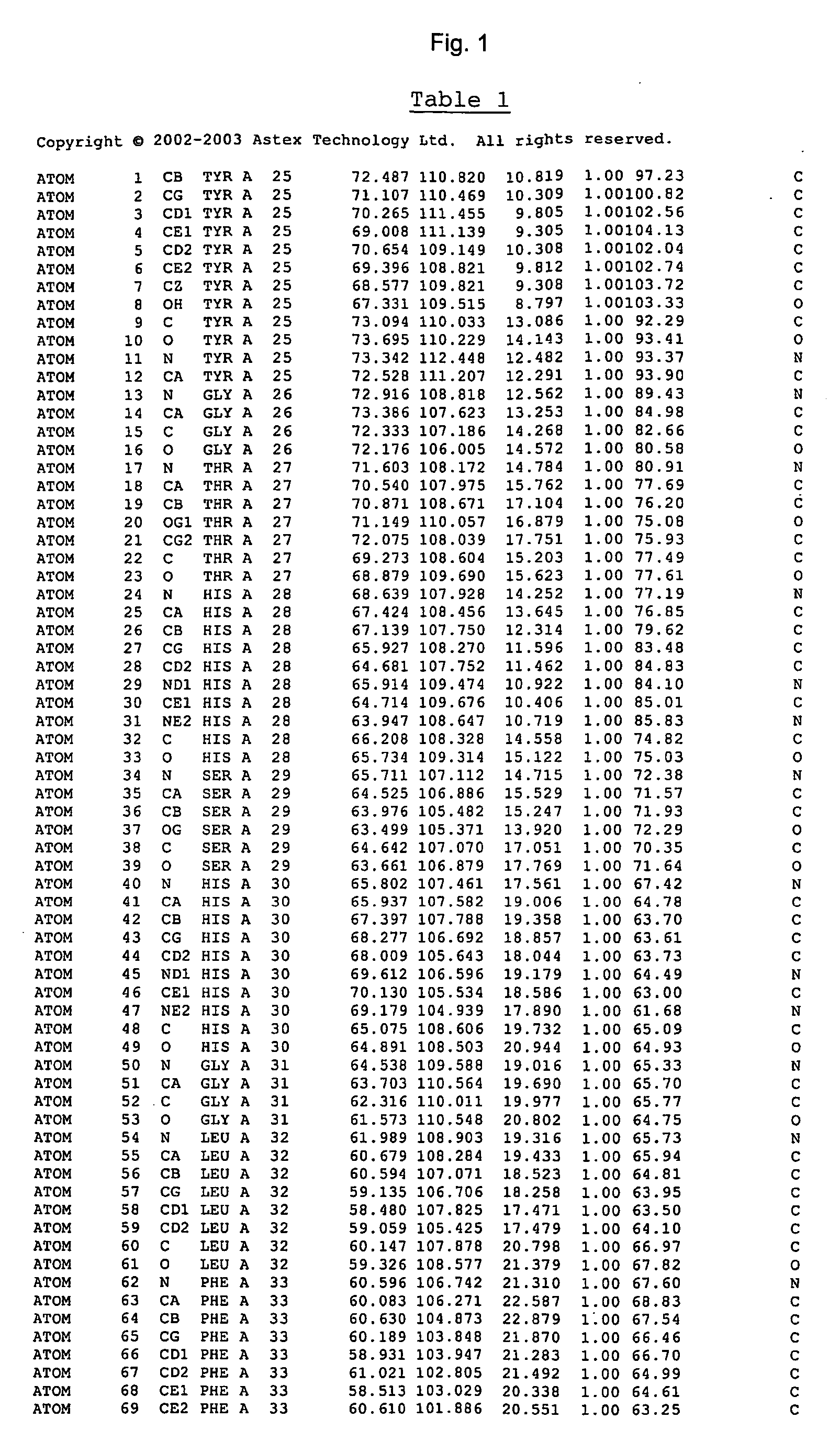
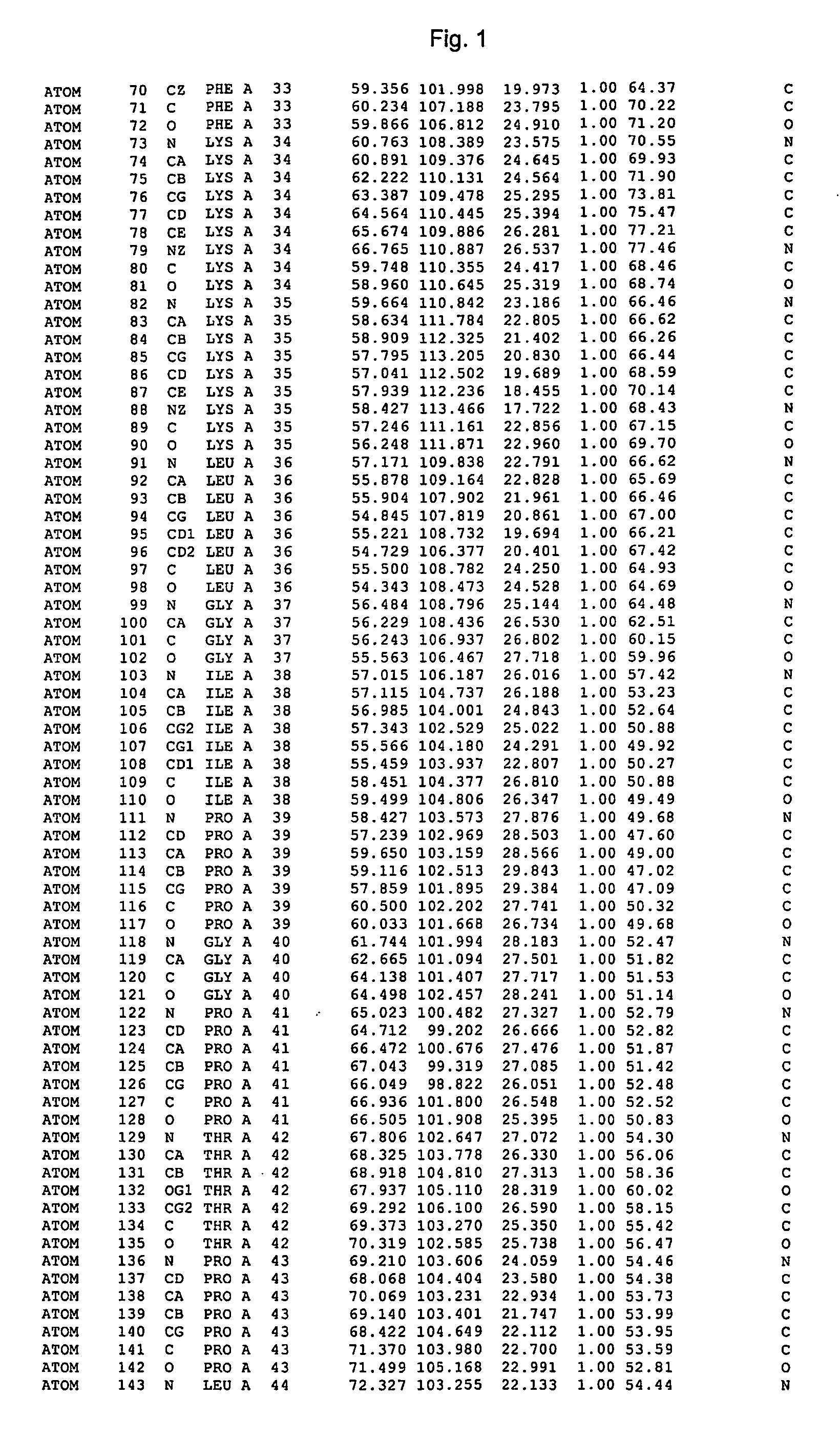
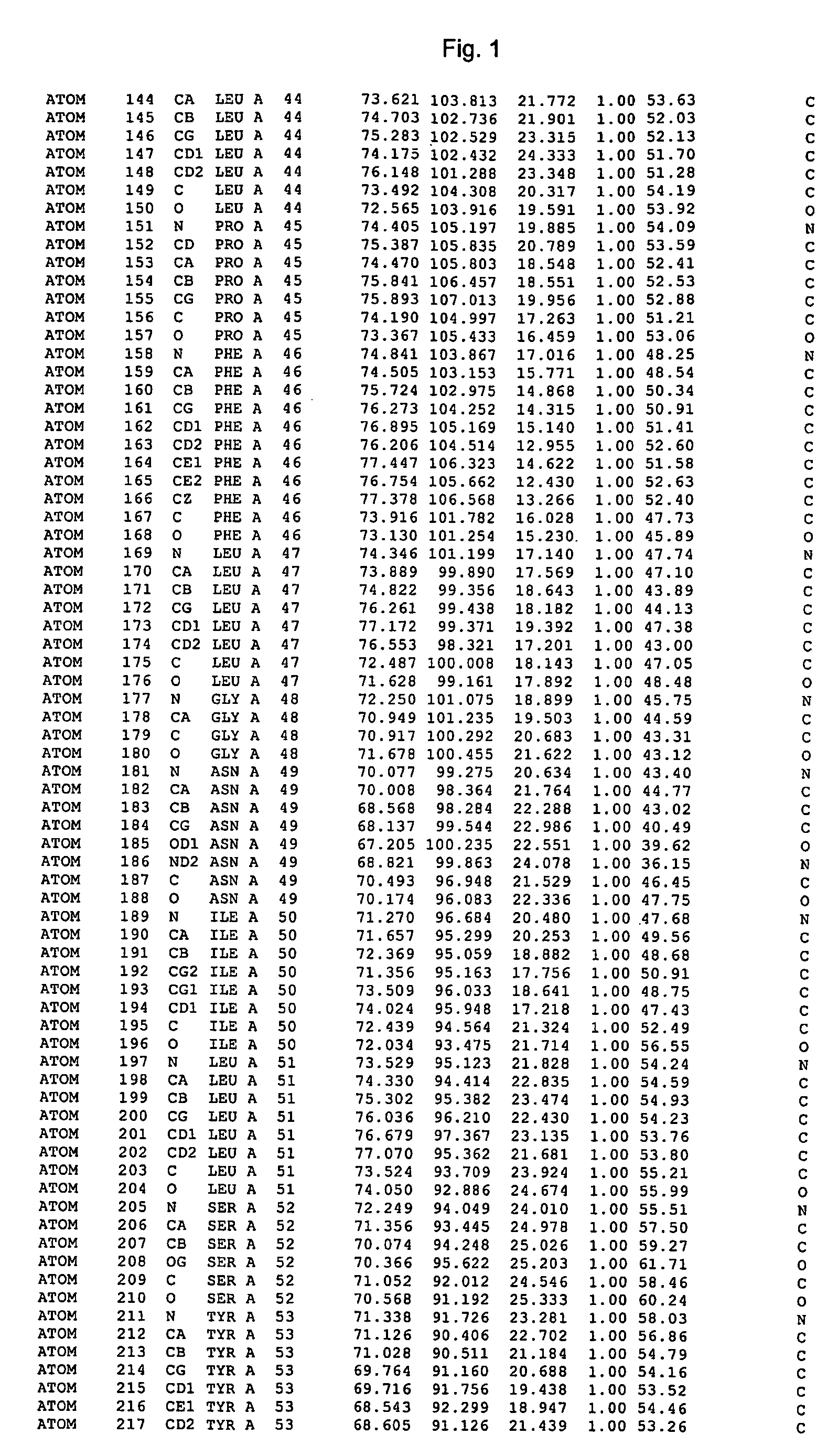
The invention provides the crystal structure of the cytochrome P450 3A4 protein molecule. The structure is set out in Tables 1-4. The structure may be used in to model the interaction of compounds such as pharmaceuticals with this protein, and to determine the structure of related cytochrome P450 molecules.

Description

[0001] The present application is a continuation of PCT / GB2005 / 001642 which claims benefit of and is a continuation-in-part of U.S. Ser. No. 10 / 833,296, filed Apr. 28, 2004, which is a continuation-in-part of application Ser. No. 10 / 690,991, filed Oct. 23, 2003, which is a itself a continuation-in-part of PCT / GB02 / 02668, filed May 30, 2002, which designated the U.S. and also claims benefit of U.S. Provisional Application Ser. No. 60 / 479,448, filed Jun. 19, 2003, and Provisional Application Ser. No. 60 / 421,063, filed Oct. 25, 2002; application Ser. No. 10 / 690,991, filed Oct. 23, 2003, is also a continuation-in-part of application Ser. No. 10 / 221,036, which was filed as a 371 of PCT / GB02 / 01575 on Sep. 9, 2002; and International Application PCT / GB02 / 01575, filed Apr. 2, 2002, claimed priority to U.S. Application Ser. Nos. 60 / 306,873 and 60 / 306,874, both filed Jul. 23, 2001 and also claimed benefit of GB 0108212.2 and GB 0108214.8, filed Apr. 2, 2001; the entire contents of each of thes...

Claims


Application Information

Patent Timeline
IPC IPC(8): G06F19/00
CPCC12Q1/26G01N2333/90245G01N33/68
Inventor WILLIAMS, PAMELAVINKOVIC, DIJANA MATAKJHOTI, HARREN
Owner ASTEX THERAPEUTICS LTD
Learn More