Impact tool

a tool and tool body technology, applied in the field of impact tools, can solve the problems of obstructing the relative movement of the two members in the axial direction, affecting the relative movement of the two members, and raising problems with noise energy of fastening objects, so as to reduce the noise of the impact tool, increase the transmission torque of the anvil, and increase the relative rotation

Inactive Publication Date: 2007-08-02
KOKI HLDG CO LTD
View PDF15 Cites 8 Cited by
  • Summary
  • Abstract
  • Description
  • Claims
  • Application Information

AI Technical Summary

Benefits of technology

The invention is an impact tool that reduces noise without compromising fastening ability. It includes a rotary impact mechanism mounted on a spindle to be rotationally driven by a motor. The impact tool includes a plurality of pawls and a damper interposed between the pawls to absorb vibration and reduce noise. The damper is formed of elliptical column-shaped damper members that are arranged in a space formed between the pawls. The damper members are designed to minimize deformation and prevent damage. The impact tool also includes a minimum sectional area between the pawls larger than the sectional area of the damper to further reduce noise. The damper is interposed between the two half members formed by halving the anvil to absorb vibration and prevent damage. The arrangement of the damper members allows for stable performance even if the damper is disconnected.

Problems solved by technology

However, the impact tool has a rotary impact mechanism for generating the rotary impact, so that it has such a serious noise as raises problems.
Here, it has been found that the noise energy from the fastening object takes a large ratio in the noise at the working time using the impact tool.
When the torque is applied to the torque transmission unit, however, a high frictional force is established between the two members thereby to obstruct the relative movement of the two members in the axial direction.
As a result, the axial force to act on the tip tool or the screw cannot be reduced so much as to make the noise reducing effect insufficient.
With this constitution, however, the facial pressure on the contact portions between the key elements and the grooves is so high as to raise the problems that the parts are prematurely worn, and that the structure is complicated to raise the manufacturing cost.

Method used


Image

  • Impact tool
  • Impact tool
  • Impact tool

Examples


Embodiment Construction

[0038]An embodiment of the invention is described in the following with reference to the accompanying drawings.

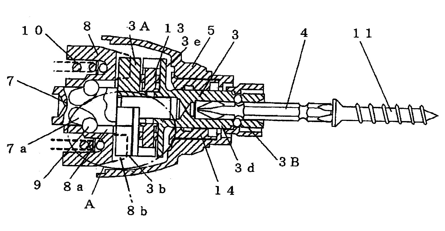
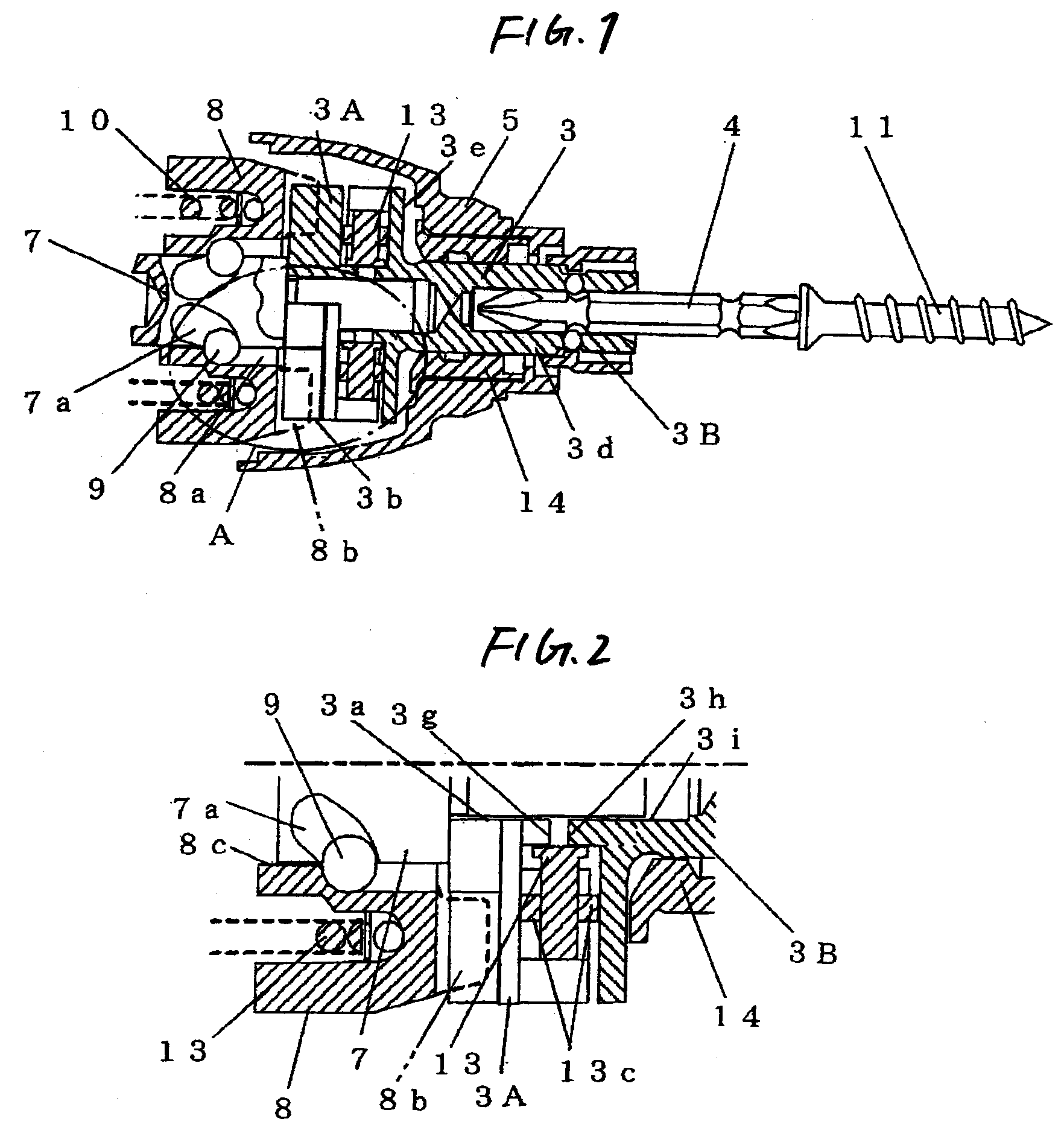
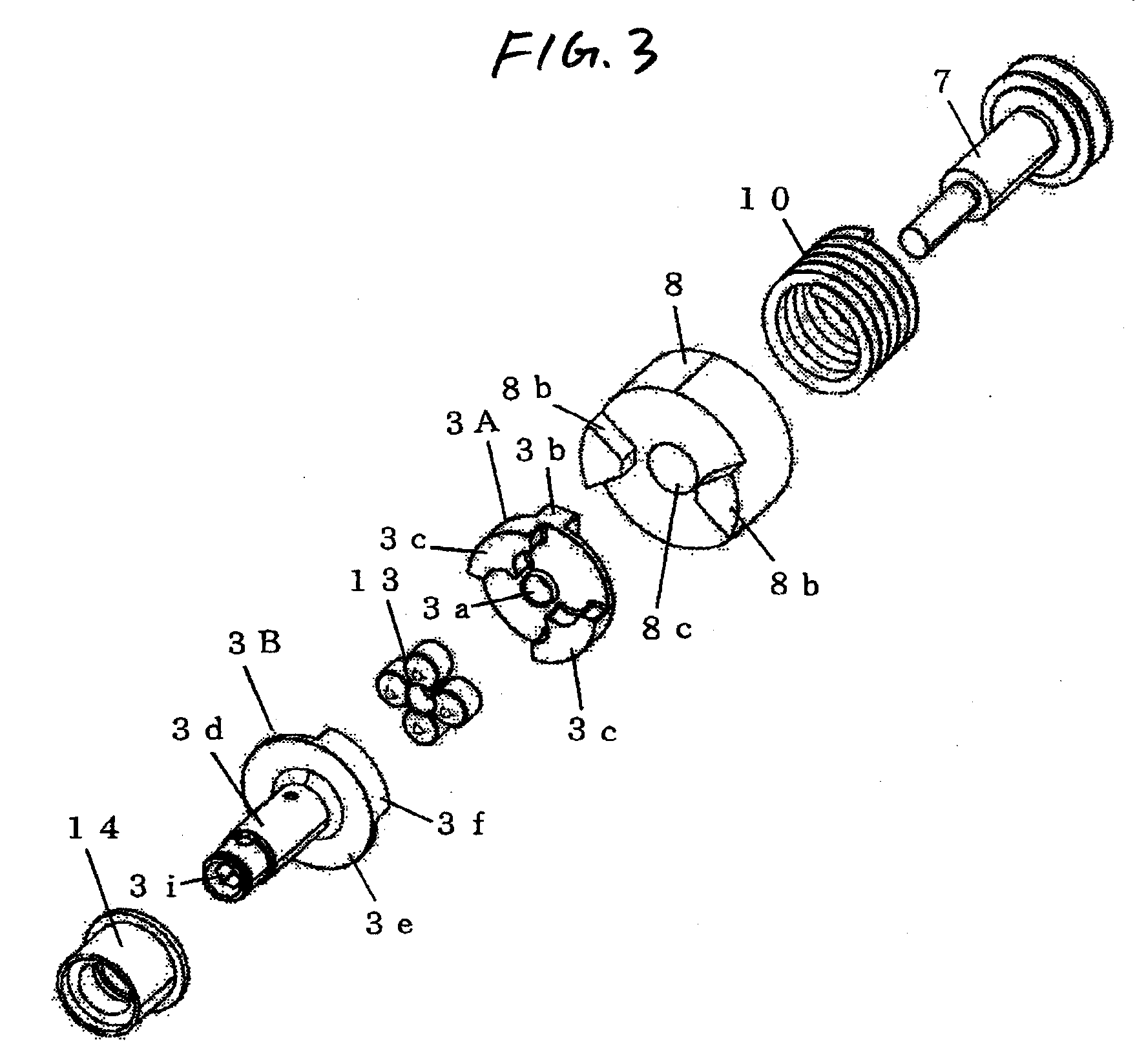
[0039]FIG. 1 is a longitudinal section of a rotary impact mechanism unit of an impact tool according to the invention; FIG. 2 is an enlarged detailed diagram of a portion A of FIG. 1; FIG. 3 and FIG. 4 are exploded perspective views of the rotary impact mechanism of the same impact tool; FIG. 5 is a sectional side elevation of an anvil of the same impact tool; FIG. 6 is a sectional view taken along line B-B of FIG. 5; FIG. 7 is a sectional view taken along line C-C of FIG. 6; FIG. 8(a) is a front elevation of a rubber damper; FIG. 8(b) is a side elevation of the same rubber damper; and FIGS. 9(a) and 9(b) are front elevations for explaining the behaviors of pawls of the anvil. In these Figures, the same elements as those shown in FIG. 10 are designated by the common reference numerals.

[0040]The impact tool according to this embodiment is a cordless hand-holdable tool having...


PUM


Abstract

An impact tool, which can realize the reduction of noise without inviting the reduction of a fastening ability and which can improve the durability of a damper while preventing its damage. The impact tool includes a rotary impact mechanism mounted on a spindle to be rotationally driven by a motor, so that rotary impact is applied to a tip tool by transmitting the rotary impact intermittently from a hammer through an anvil to the tip tool. A plurality of pawls are formed on two half members of the anvil in the axial direction. A rubber damper is disposed in a space between the pawls arranged alternately in the circumferential direction of the two half members. The minimum sectional area of the space formed between the pawls is set larger than the sectional area of the rubber damper.

Description

BACKGROUND OF THE INVENTION[0001]The present invention relates to an impact tool for generating a rotary impact to perform desired works such as a screw fastening operation.[0002]The impact tool as one mode of the electric tool performs a screwing operation by generating a rotary impact with a motor as a drive source to rotate a tip tool and by applying the impact intermittently to the tip tool. The impact tool is widely used at present because it is advantageous in a small reaction and in a high fastening ability. However, the impact tool has a rotary impact mechanism for generating the rotary impact, so that it has such a serious noise as raises problems.[0003]FIG. 10 is a longitudinal section showing a general impact tool used in the prior art.[0004]The impact tool of the prior art shown in FIG. 10 is enabled to transmit the rotary impact intermittently to a tip tool 4 thereby to perform the screwing operation, by using a battery pack 1 as an electric source and a motor 2 as the ...

Claims


Application Information

Patent Timeline
Patent Type & Authority Applications(United States)
IPC IPC(8): C07C2/64
CPCB25B21/02B25B21/023
Inventor MURAKAMI, TAKUHIROKAMIMURA, JUNICHIOOMORI, KATSUHIROOHTSU, SHINKIINAGAWA, HIROTO
Owner KOKI HLDG CO LTD
Why Eureka
Try Eureka