
Keel type ram for use in internal batch mixers with tangential rotors

a tangential rotor and ram technology, applied in the field of improved rams, can solve the problems of significant wear on the ram and the throat of the mixing chamber, noise, wear and mechanical impact damage, etc., and achieve the effects of reducing noise, reducing rotational forces on the ram, and reducing wear and impact damag

Active Publication Date: 2007-08-02
FARREL CORP
View PDF17 Cites 8 Cited by
  • Summary
  • Abstract
  • Description
  • Claims
  • Application Information

AI Technical Summary

Benefits of technology

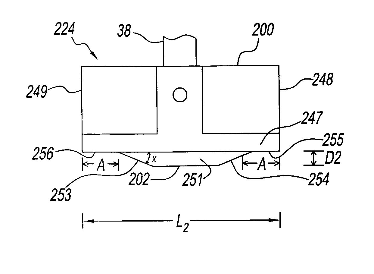
[0006] This invention provides a ram for use in a mixer with counter-rotating non-intermeshing rotors on which the central portion of the bottom face or surface of the ram utilizes a protruding apex, either a point or a line produced by a “V” or similar shape, that protrudes a given distance into the mixing chamber and on which the end portions of the ram are either horizontal such that they do not protrude into the mixing chamber at all or are otherwise shaped such that they protrude into the mixing chamber less than the apex of the central portion of the ram. A mixer utilizing the improved ram substantially reduces the rotational forces on the ram, producing lower noise levels and reduces wear and impact damage. At the same time, the improved ram provides similar dispersive mixing and improved distributive mixing characteristics to a traditional “V” shape ram that extends into the mixing chamber an equal distance along the entire lateral bottom surface of the ram.

Problems solved by technology

While, for traditional non-synchronous driven rotor internal batch mixers operated at relatively low rotor rotation speeds these varying cyclical rotational forces have not posed significant difficulties, the inventors have found this not to be the case for synchronous driven rotor internal batch mixers operating with increased rotor speeds.
As the rotors in the mixing chamber turn, the material being mixed is moved across resulting in substantial, significant noise and vibration of the ram against the sides of mixing chamber and housing associated therewith during operation of the internal batch mixer and resulting in significant wear on the ram and throat of the mixing chamber.
All this movement creates noise, wear and mechanical impact damage.

Method used


Image

  • Keel type ram for use in internal batch mixers with tangential rotors
  • Keel type ram for use in internal batch mixers with tangential rotors
  • Keel type ram for use in internal batch mixers with tangential rotors

Examples


Embodiment Construction

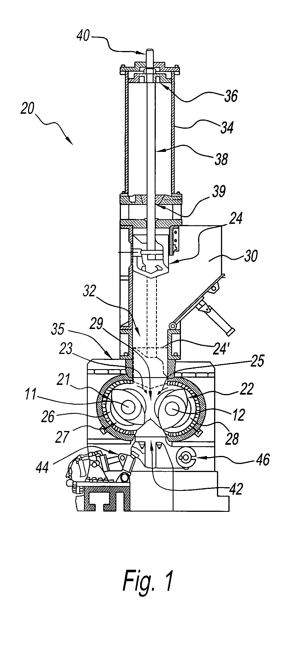
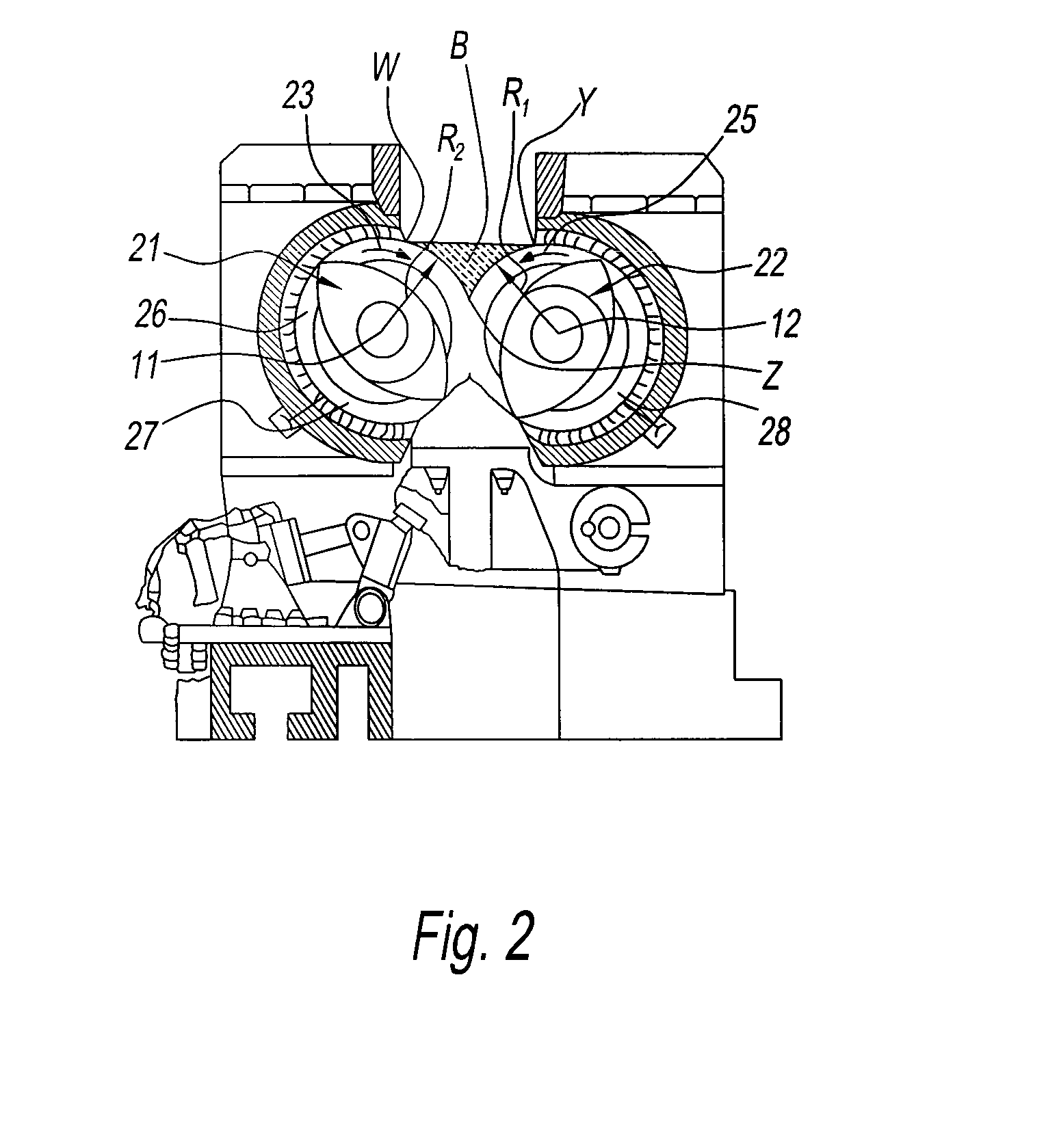
[0038] As shown in FIG. 1, a high intensity internal mixing machine of the batch type, generally indicated at 20, in which a vertically reciprocatable ram 24 embodying the present invention is movable between a raised position shown in FIG. 1 and a lowered operating position 24′ shown in dashed outline. This ram 24 is used to move ingredients to be mixed down into a mixing chamber 26. In its operating position 24′, the ram opposes the forces exerted by materials in the mixing chamber 26 as they are being thoroughly and intensely mixed by wings on the two counter-rotating, non-intermeshing rotors 21 and 22, which are turned, as shown by arrows 23 and 25, about spaced parallel horizontal axis 11 and 12. The left rotor 21 as seen in FIG. 1, is turned in a clockwise direction about its axis 11 and the right rotor 22 in a counterclockwise direction about its axis 12. The mixing chamber 26 is shaped to accommodate these two tangential rotors and includes left and right chamber cavities 27...


PUM

PropertyMeasurementUnit
angleaaaaaaaaaa
lateral lengthaaaaaaaaaa
lengthaaaaaaaaaa

Abstract

This invention provides a ram for use in a mixer with counter-rotating non-intermeshing rotors on which the central portion of the ram utilizes a apex, either a point or a line produced by a “V” or similar shape, that protrudes a given distance into the mixing chamber and on which the end portions of the ram are either horizontal such that they do not protrude into the mixing chamber at all or are otherwise shaped such that they protrude into the mixing chamber less than the apex of the central portion of the ram.

Description

FIELD OF THE INVENTION [0001] This invention relates to an improved ram for use especially in internal batch mixers with counter-rotating, non-intermeshing, tangential rotors. The improved rams of this invention provide equal or better distributive and dispersive mixing while reducing vibration of the ram and decreasing mixer noise, and permit increased batch sizes. The invention also relates to internal batch mixing machines employing the improved rams and to processes for mixing polymeric and / or rubber materials and optionally additives using an internal batch mixing machine employing the improved rams of this invention. BACKGROUND TO THE INVENTION [0002] This invention relates to the field of high intensity internal mixing machines of the batch type having a mixing chamber shaped to accommodate two counter-rotating, non-intermeshing, tangential winged rotors. The batch of ingredients to be mixed into a homogeneous mass is fed down into the mixing chamber through a vertical chute ...

Claims


Application Information

Patent Timeline
Patent Type & Authority Applications(United States)
IPC IPC(8): B29B7/18B01F7/00
CPCB29B7/246B29B7/183B29B7/263
Inventor BORZENSKI, FRANKPETERSON, STEPHEN E.NEUGEBAUER, JOHN
Owner FARREL CORP
Learn More