Ground-fault resistance measurement circuit and ground-fault detection circuit
- Summary
- Abstract
- Description
- Claims
- Application Information
AI Technical Summary
Benefits of technology
Problems solved by technology
Method used
Image
Examples
Embodiment Construction
[0033]Hereinafter, a ground-fault resistance measurement circuit according to an embodiment of the present invention will be described with reference to the attached drawings. In each figure, component elements are identical with each other if given the same reference characters and numerals. Thus, their description is omitted.
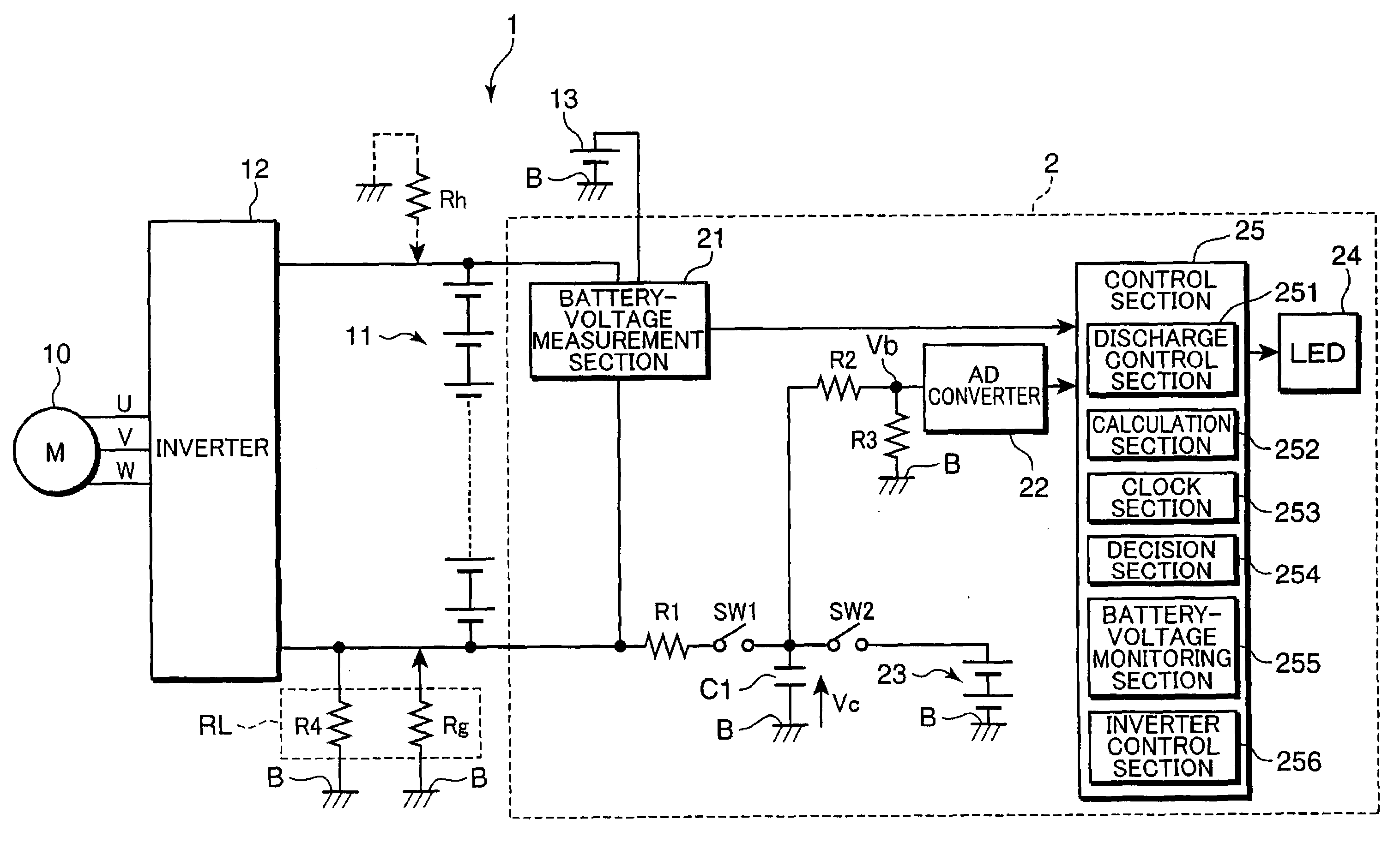
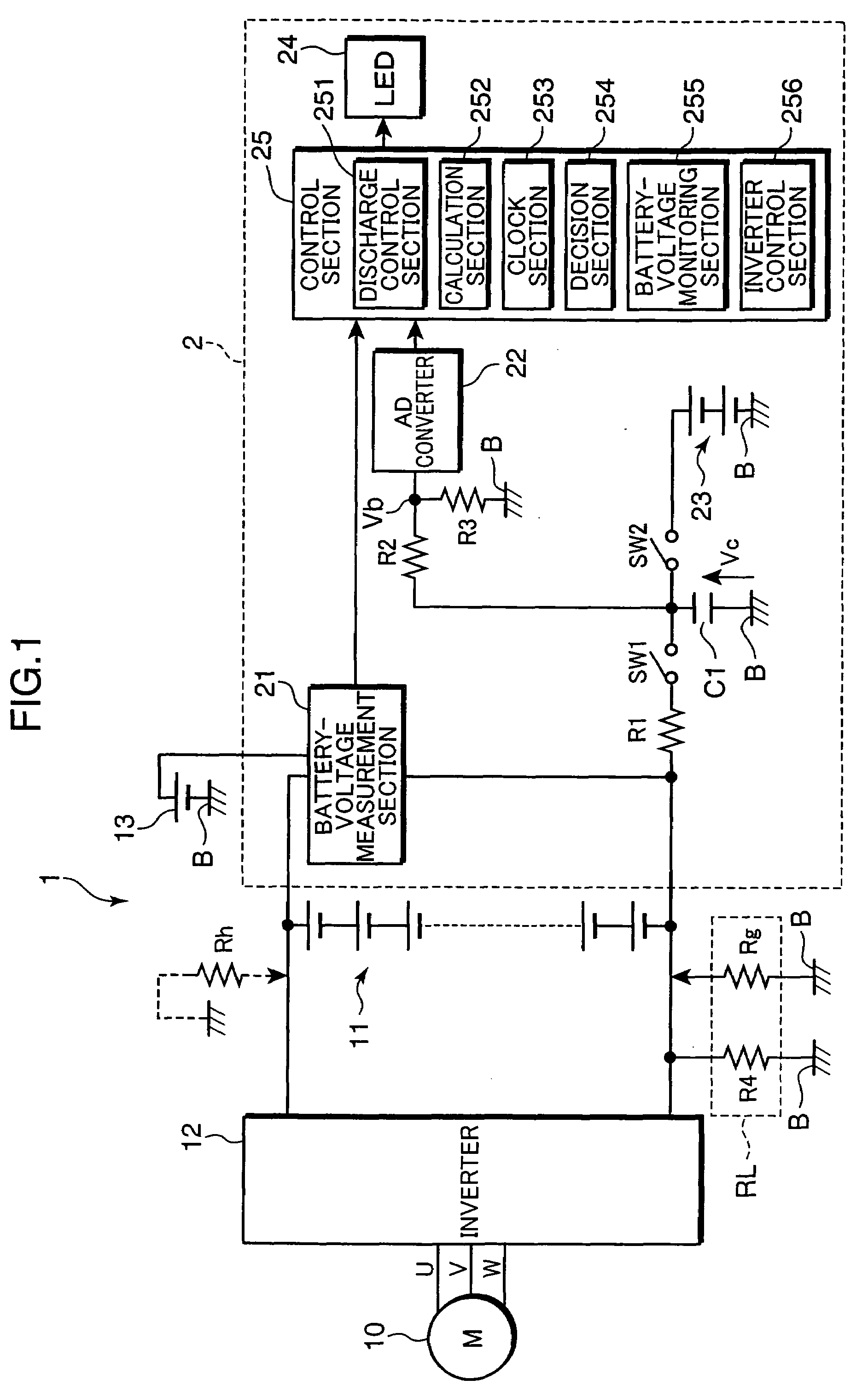
[0034]FIG. 1 is a circuit diagram, showing an example of the configuration of a ground-fault detection circuit provided with the ground-fault resistance measurement circuit according to the embodiment of the present invention. A ground-fault detection circuit 2 shown in FIG. 1 is mounted, for example, in a vehicle 1 such as an electric automobile, like a hybrid car or a fuel-battery vehicle. The ground-fault detection circuit 2 measures a resistance value RL of a ground-fault resistance RL which corresponds to a resistance between the charge section and a vehicle body B. Based on this resistance value RL, it detects a ground fault being generated.
[0035]The veh...
PUM
 Abstract
Description
Claims
Application Information
 - R&D
- Intellectual Property
- Life Sciences
- Materials
- Tech Scout
- Unparalleled Data Quality
- Higher Quality Content
- 60% Fewer Hallucinations
Browse by: Latest US Patents, China's latest patents, Technical Efficacy Thesaurus, Application Domain, Technology Topic, Popular Technical Reports.
© 2025 PatSnap. All rights reserved.Legal|Privacy policy|Modern Slavery Act Transparency Statement|Sitemap|About US| Contact US: help@patsnap.com


