Light emitting device
- Summary
- Abstract
- Description
- Claims
- Application Information
AI Technical Summary
Benefits of technology
Problems solved by technology
Method used
Image
Examples
embodiment mode 1
[0041] In this embodiment mode, a structure of a light emitting element in which light emitting units are stacked is explained.
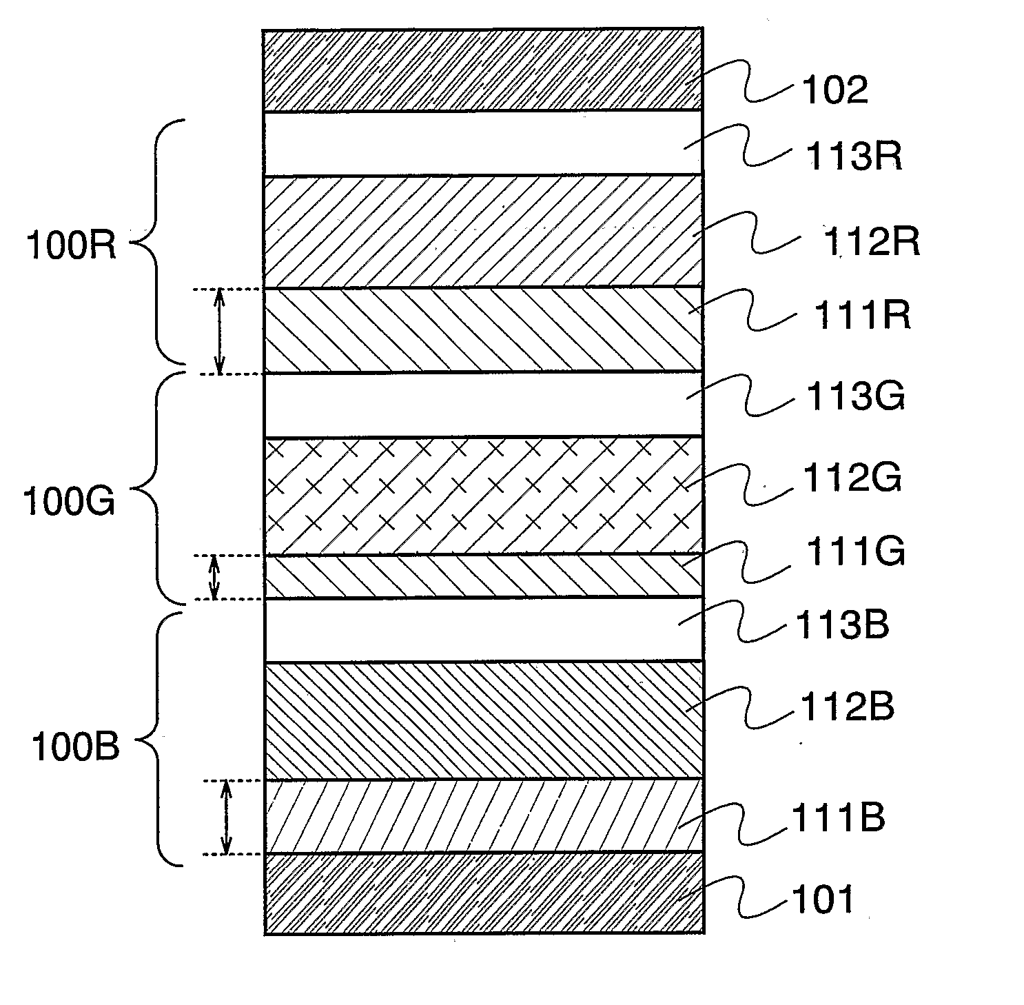
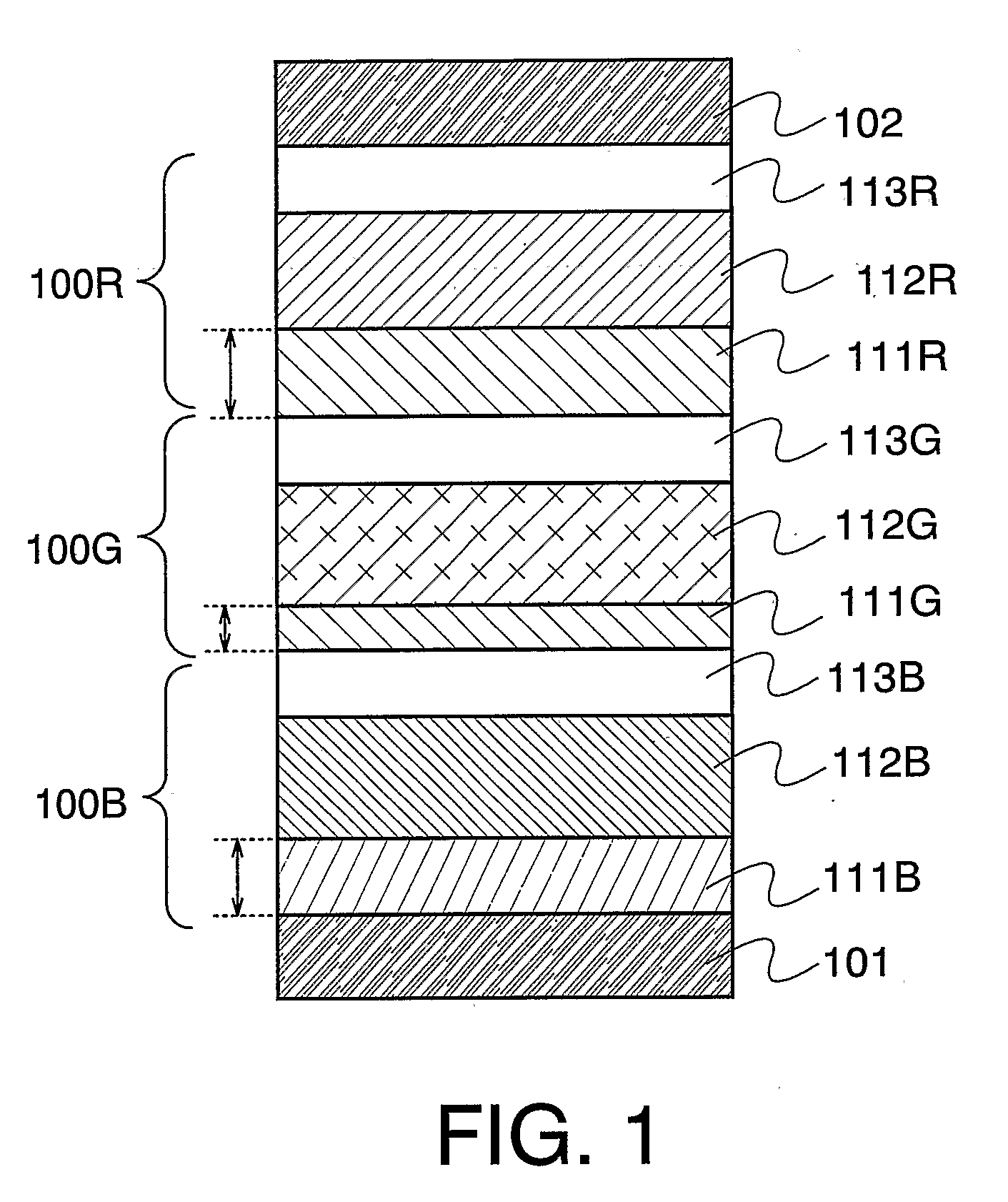
[0042]FIG. 1 shows a light emitting element in which a first light emitting unit 100B, a second light emitting unit 100G, and a third light emitting unit 100R are sequentially stacked between a first electrode 101 and a second electrode 102. The colors of light emitted from the light emitting units 100B, 100G, and 100R are not limited in particular. In this embodiment mode, however, a case where the first light emitting unit exhibits blue emission, the second light emitting unit exhibits green emission, and the third light emitting unit exhibits red emission is explained in this embodiment mode. The light emitting element in which light emitting units are stacked indicates a state where two or more light emitting units are stacked. In this embodiment mode, a state where three light emitting units are stacked is explained; however, the present invention is n...
embodiment mode 2
[0058] In this embodiment mode, a structure of a light emitting element which is different from that in the above-described embodiment mode is explained.
[0059] According to the present invention, a light emitting element in which light emitting units are stacked is not required to be applied to all light emitting elements formed over a substrate. A distance from each of light emitting layers to a first electrode 101 can be approximately oddly multiplied ¼ wavelength by controlling a thickness of a first layer 111 for at least one light emitting element, and accordingly, a state where luminous output efficiency is high can be obtained, luminous efficiency at the same current density can be enhanced, and density of current which is applied can be kept low. As a result of keeping current density low, the lifetime of the light emitting element can be improved. In this embodiment mode, a case where one light emitting element which exhibits one luminescent color is a light emitting eleme...
embodiment mode 3
[0068] In this embodiment mode, a case where a stacked layer type light emitting element is applied to a light emitting element which exhibits different luminescent color from that in the above embodiment mode is explained.
[0069] In the present invention, a stacked layer type light emitting element may be used for an element except a first light emitting element 100B. For example, a single layer type light emitting element may be used as a light emitting element 100G which exhibits luminescent color with high sensitivity with respect to human eyes such as green emission, and accordingly, the light emitting element 100G may have a structure in which the number of light emitting layers included between a pair of electrodes is smaller than that of the stacked layer type light emitting elements 100R and 100B which exhibit red emission or blue emission, respectively.
[0070] The explanation of another structure is omitted since it is similar to the above embodiment mode.
[0071] In the st...
PUM
 Abstract
Description
Claims
Application Information
 - R&D
- Intellectual Property
- Life Sciences
- Materials
- Tech Scout
- Unparalleled Data Quality
- Higher Quality Content
- 60% Fewer Hallucinations
Browse by: Latest US Patents, China's latest patents, Technical Efficacy Thesaurus, Application Domain, Technology Topic, Popular Technical Reports.
© 2025 PatSnap. All rights reserved.Legal|Privacy policy|Modern Slavery Act Transparency Statement|Sitemap|About US| Contact US: help@patsnap.com


