Brake flush machine with ordered cylinder extraction

Inactive Publication Date: 2007-08-02
NORCO INDS
View PDF5 Cites 9 Cited by
  • Summary
  • Abstract
  • Description
  • Claims
  • Application Information

AI Technical Summary

Benefits of technology

[0009] The processor manipulates the vacuum pump and manifold valves in order to extract old fluid from the brake system in a predetermined order, beginning with the longest path between the master cylinder and the respective brake element (rear passenger wheel), and ending with the shortest path (front driver wheel), followed by the ABS element. In addition to the predetermined order of the old fluid extraction, the processor controls the timing of the fluid extraction based on the distance to the master cylinder, such that the rear wheel brake elements have a longer fluid extraction period due to the greater quantity of total fluid in the line, as compared with the short line between the master cylinder and the front driver wheel. Each line has a successively shorter flush period coinciding with shorter fluid lines containing less fluid to flush. This feature saves time and new fluid, because the each line is subjected only to the necessary flushing period to extract the old fluid without delaying or flushing new fluid entering the system.

Problems solved by technology

Moisture in the brake line can form ice at low temperatures that can lead to a loss of fluid flow.
Unwanted water absorbed into the brake fluid leads to a reduced boiling temperature and the formation of ice, which causes poorer brake performance.
Contamination is also an issue for effective operation of the braking system, where breakdown of the fluid can lead to premature wear of piston seals, hoses and other parts.
Additionally, oxidation of the brake fluid upon exposure to air can result in a reduced boiling temperature.
Additionally the additive packages used in brake fluids to reduce oxidation, foaming and corrosion are denigrated by the presence of moisture.
Because the introduction of unwanted moisture and contaminants in the braking system is unavoidable, automobile manufactures recommend that automotive brake fluid should be replaced and the brake system flushed of contaminants when the moisture level in the brake fluid exceeds a predetermined threshold, when contamination is present, or when the hydraulic fluid's inhibitor package has deteriorated.
Through use, brake fluid can become discolored due to contamination from dirt and disintegrating rubber seals.
Furthermore, as the brake fluid absorbs moisture from the air, its boiling point is lowered and corrosion may initiate inside the brake system.
A reduced boiling point can result in the brake fluid boiling under extreme conditions such as a long downhill stretch of intermittent braking.
Bubbles in the brake fluid due to boiling reduce the brake effectiveness because gas is very compressible as compared with fluid, and thus the force applied by the pressurized brake fluid in the brake lines is lessened as the amount of gas in the system increases.
Particulate matter such as airborne dust and rubber seal fragments can also collect within the fluid filled brake lines preventing proper sealing of valves within the braking system.
Brake fluid exposed to ambient air can absorb moisture resulting in an immediate loss of the brake fluid's effectiveness.
Unfortunately this known method can release pollutants into the air and exposes the operator to potentially harmful fluids and vapors.
The job typically took up to thirty minutes and was not cost effective in that two workers must be present for essentially the entire job.
Moreover, the brake fluid exchange process did not account for the varying lengths of brake line, adding inefficiencies and undue delays in the fluid exchange process.

Method used


Image

  • Brake flush machine with ordered cylinder extraction
  • Brake flush machine with ordered cylinder extraction
  • Brake flush machine with ordered cylinder extraction

Examples


Embodiment Construction

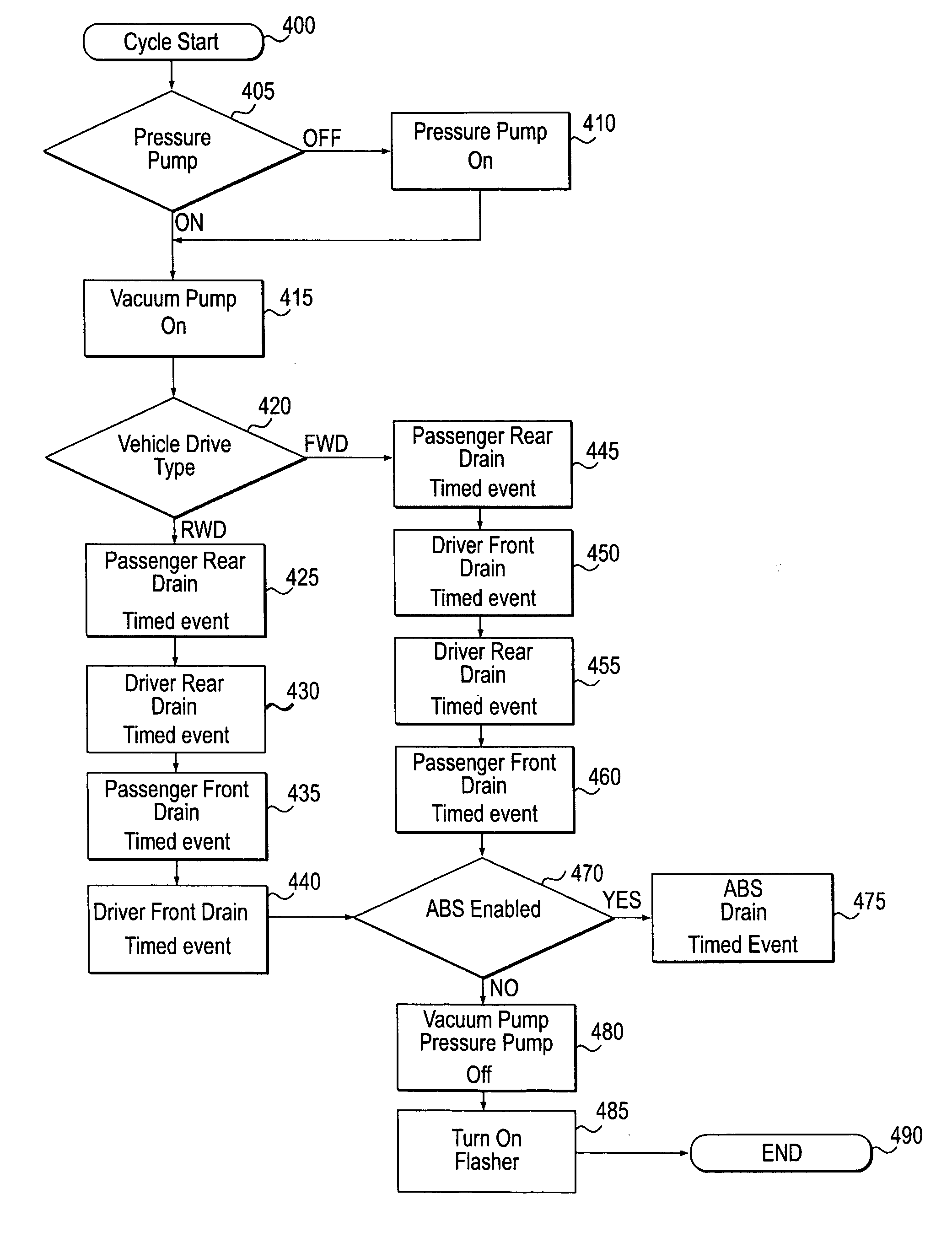
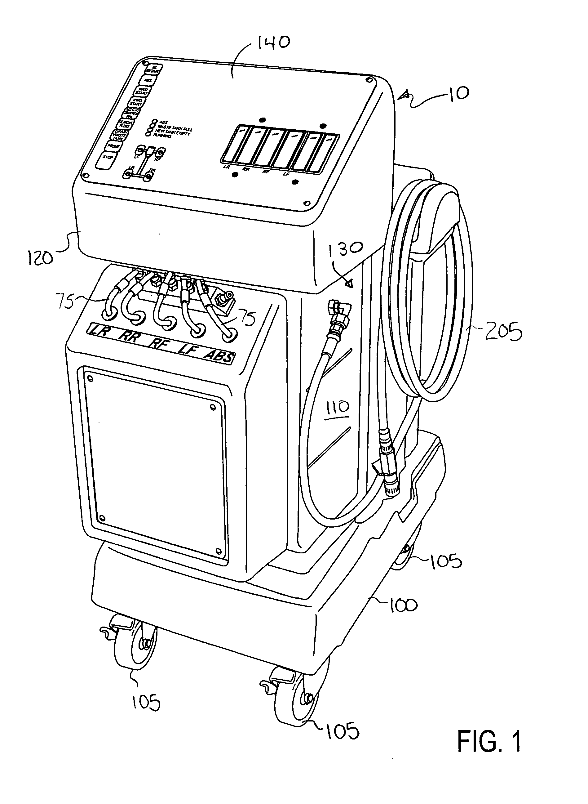
[0015]FIG. 1 illustrates an automatic brake flush machine according to the teachings of the present invention. The brake machine is a combination of plumbing components (pumps, tubing, valves) and electrical components (processors, electrical cables, display equipment) enclosed in a durable plastic housing. The housing 10 includes a platform 100 with four caster wheels 105 that allow the machine to be rolled quickly into position as needed to service the vehicle. On the platform 100 is a cabinet 110 that encloses a twenty quart waste fluid tank 70, a seven quart new fluid tank 20, an electrical system powered by a twelve volt battery such as those found in most passenger vehicles, a vacuum pump 55, a pressure pump 30, and a five valve solenoid 95 for controlling the extraction of waste fluid from the cylinders of the respective wheels and the ABS system 60.

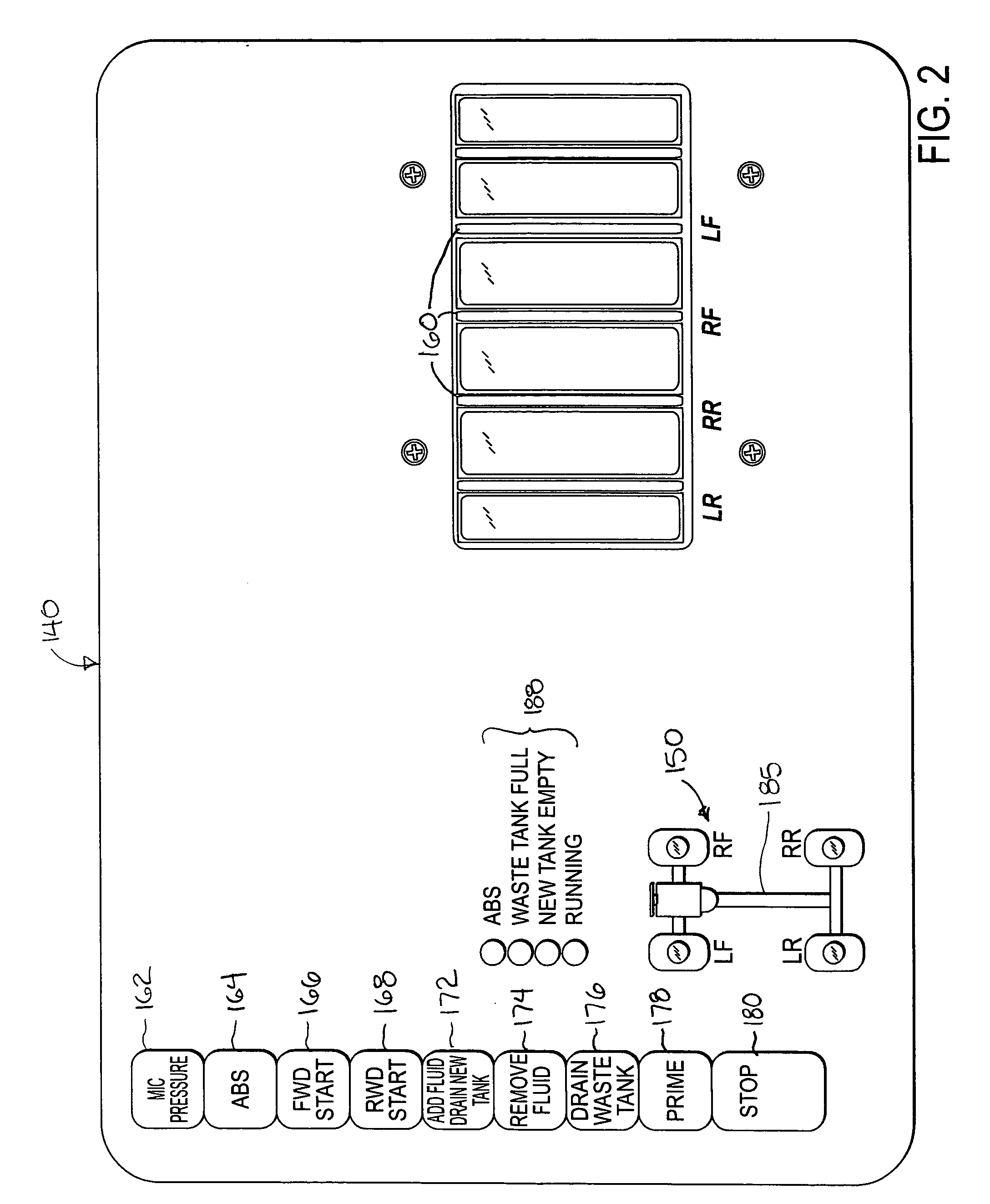
[0016] The cabinet 110 includes a podium 120 having a column 130 and control area 140. The controls for operating the machine a...


PUM

PropertyMeasurementUnit
Distanceaaaaaaaaaa

Abstract

A brake fluid flush machine is adapted to simultaneously supply fresh brake fluid and vacuum used brake fluid in a vehicles braking system while controlled by a processor to allow a single worker to complete the fluid exchange operation. The automatic brake fluid exchange machine comprises a used fluid tank, a new fluid tank, a manifold connectable to four secondary brake cylinders corresponding to a front driver's side wheel, a front passenger's side wheel, a rear driver's side wheel, and a rear passenger's side wheel, a suction pump connecting the manifold to said used fluid tank for draining used brake fluid from said four secondary brake cylinders, a pressure pump connecting the new fluid tank to the master cylinder, and a processor. The processor is configured to control the fluid exchange by sequentially opening and closing valves that couple the four secondary brake cylinders with the suction pump, where the valve connected to the rear passenger's side cylinder is first opened and then closed, followed by opening and closing of the valve connected to the rear driver's side cylinder, followed by the opening and closing of the valve connected to the front passenger's side cylinder, and then opening and closing of the valve connected to the front driver's side cylinder.

Description

FIELD OF THE INVENTION [0001] The present invention is directed to the field of automotive service machines, and more particularly to a machine for flushing and replenishing brake fluid in a braking system. BACKGROUND OF THE INVENTION [0002] Hydraulic braking systems are prevalent among many current vehicles including passenger vehicles. Such braking systems have a master cylinder that holds a brake fluid, and auxiliary cylinders connected the master cylinder to each wheel's dedicated cylinder via a brake line. When the brake pedal of an automobile is actuated, a piston in the master cylinder translates to displace hydraulic brake fluid in the primary cylinder, which in turn forces brake fluid through the brake lines to the auxiliary cylinders at each wheel. The brake fluid in the brake lines is pressurized and imparts a hydraulic force actuating the auxiliary cylinders, which in turn forces a brake pad against the brake drum or rotor of the automobile's wheel. The frictional force ...

Claims


Application Information

Patent Timeline
IPC IPC(8): B65B3/04
CPCB60T17/222
Inventor FLOURNOY, MATTHEW MICHAEL
Owner NORCO INDS
Why Eureka
Try Eureka