
Far infrared heater

Inactive Publication Date: 2007-07-26
CHANG CHARVES
View PDF12 Cites 7 Cited by
  • Summary
  • Abstract
  • Description
  • Claims
  • Application Information

AI Technical Summary

Benefits of technology

[0009] The primary objective of the present invention is to provide a far infrared heater that is a heating structure able to emit far infrared rays to all sides, so that an effect that a user fast warms up can be achieved.

Problems solved by technology

In the busy as well as tensed up industrial and commercial society, some people who work and seat in offices for long periods are subjected to having bad blood circulation that makes abnormal body functions; while some other people having inferior body constitutions are subjected to having phenomenon of cool hands and feet, this phenomenon is more serious in winters.
However, in fact, not all people have time and constancy for sporting.
However, a conventional heating pad mainly has therein separated heating wires extending to and fro, it is unable to give the heating pad an uniform temperature when being heated; and the heating pad mainly is used to cover an area of a body, if it is used as a foot pad, it not only is subjected to getting dirty, but also looks complicated by providing with a manual switch.
A conventional foot steeper can only get an effect of heating for a user after adding water and having the water heated, this not only renders large volume of the entire foot steeper, but also is more cumbersome for use.
Moreover, none of the two above stated heating devices uses far infrared ray for heating, they only take advantage of heat transmission, their effect of improving blood circulation of bodies are not good.

Method used


Image

  • Far infrared heater
  • Far infrared heater
  • Far infrared heater

Examples


Embodiment Construction

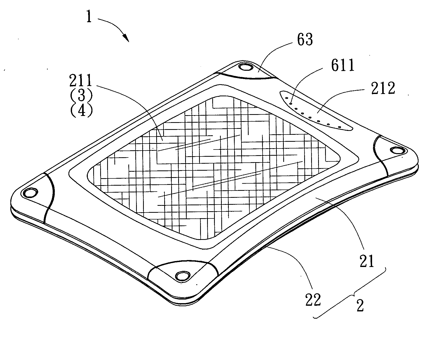
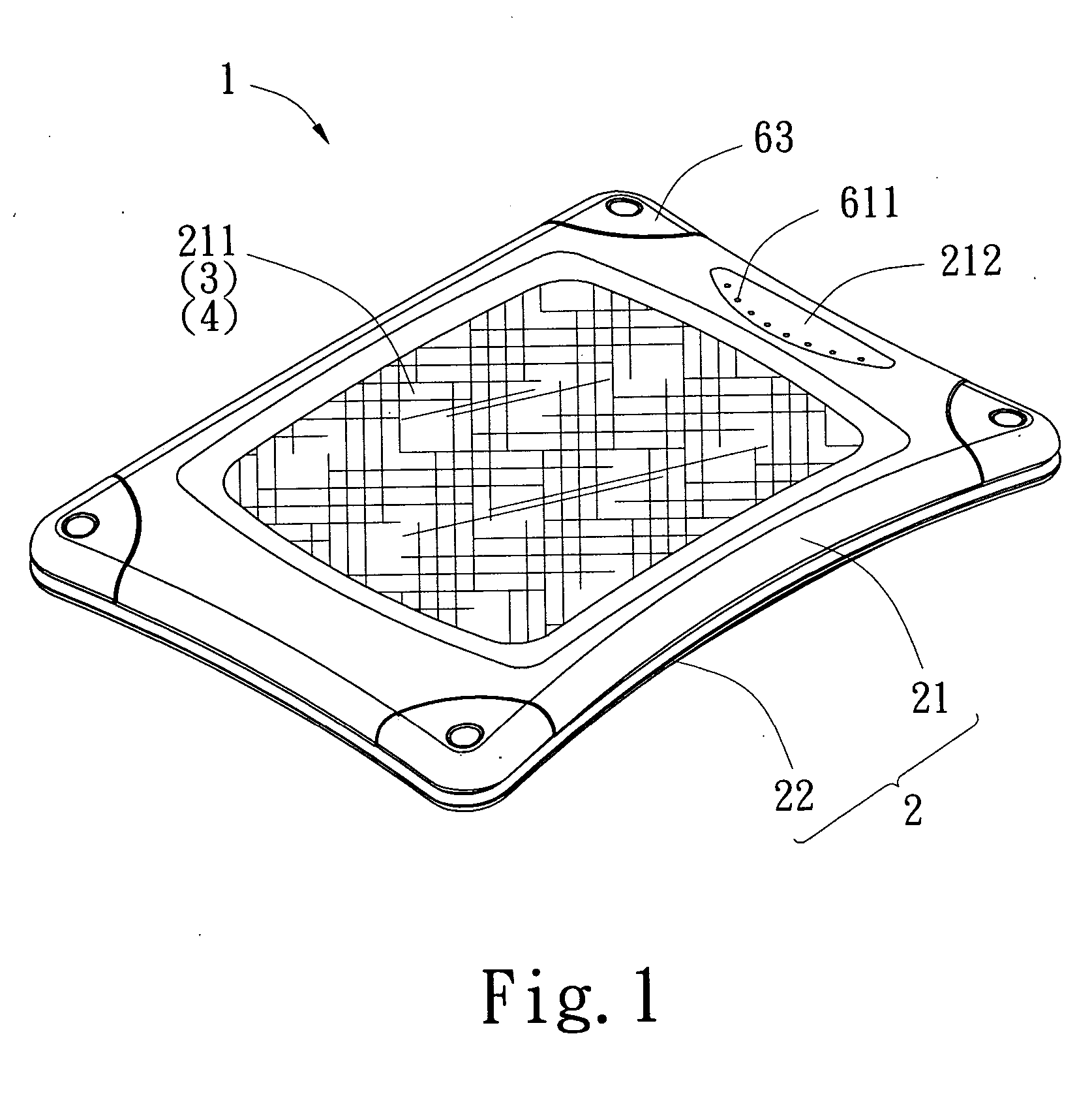
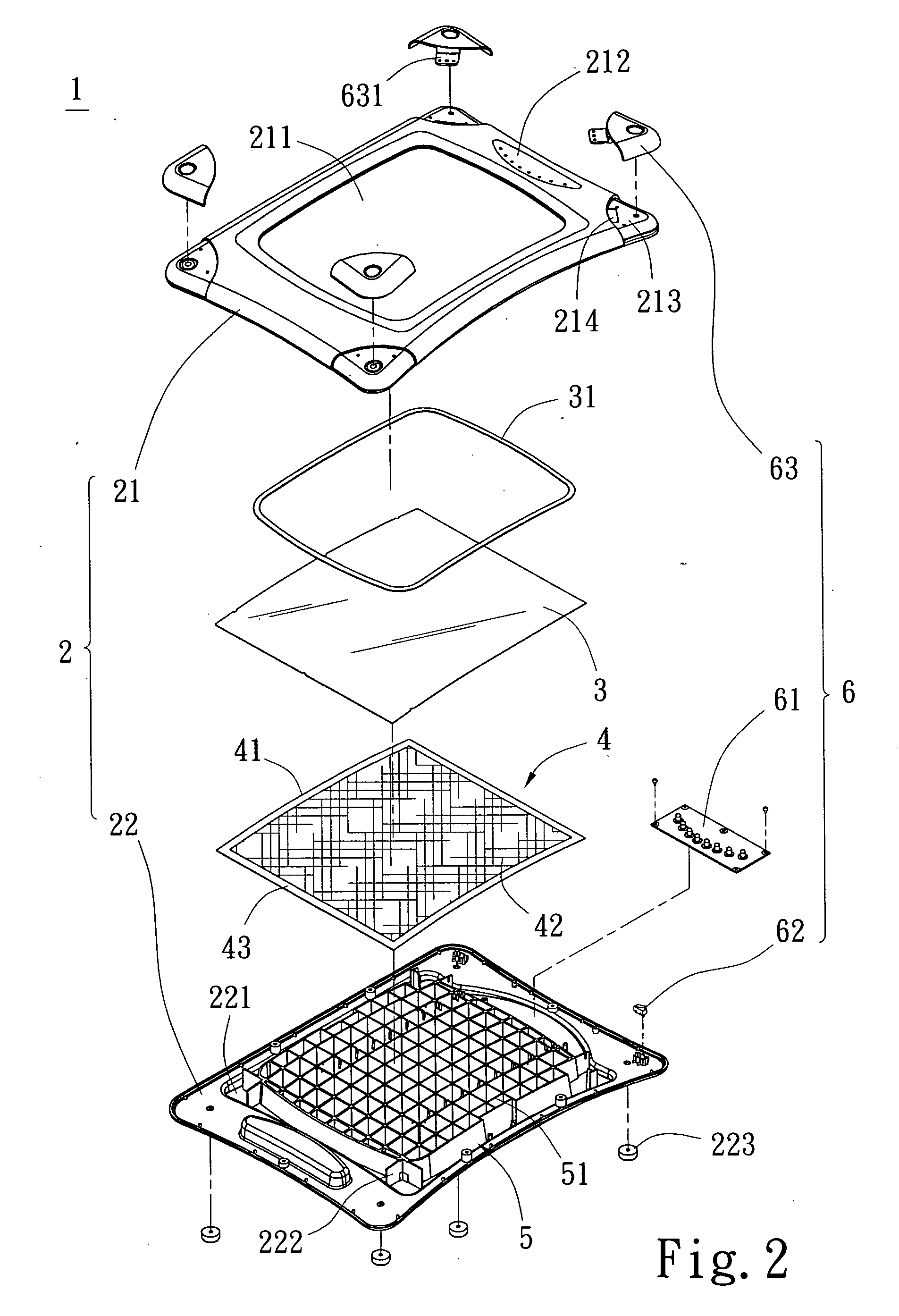
[0018] Referring to FIGS. 1 and 2 which depict a preferred embodiment of a far infrared heater 1 of the present invention, the far infrared heater 1 comprises a housing 2, a panel 3, a far infrared heating member 4, a supporting structure 5 and a control device 6.

[0019] The housing 2 is an upwardly arched rectangular member, it includes an upper lid 21 and a lower base 22 connected with each other. The upper lid 21 is provided centrally on its top with an opening 211 which is generally rectangular and renders communicating of its upper area with its lower area; the upper lid 21 is provided centrally on its top with a display screen 212, and its four corners each has a dent 213 to leave a notch 214. The base 22 is generally rectangular, and is provided centrally on its top with a recess 221, the recess 221 has at each of its four corners a positioning member 222. The base 22 has on its bottom surface a plurality of supporting blocks 223 to support the base 22 and the upper lid 21.

[...


PUM


Abstract

A far infrared heater having a housing provided on its top with an opening, a far infrared heating member is provided beneath the opening; the far infrared heating member is provided beneath it with a supporting structure to support the far infrared heating member able to emit far infrared rays to all sides. The far infrared heating member is electrically connected with a control device that includes a touch control plate provided on the housing for direct pressing by a user. Hence the far infrared heating member can emit far infrared rays to radiate out from of the opening of the housing when it is turned on.

Description

BACKGROUND OF THE INVENTION [0001] 1. Field of the Invention [0002] The present invention relates to a far infrared heater, and more particularly to a far infrared heater having a far infrared heating member supported by a supporting structure able to emit far infrared rays to all sides, the far infrared rays can be radiated out from an opening of a housing of the heater; the heater can be used at a foot, a shoulder or some other areas of the body. [0003] 2. Description of the Prior Art [0004] In the busy as well as tensed up industrial and commercial society, some people who work and seat in offices for long periods are subjected to having bad blood circulation that makes abnormal body functions; while some other people having inferior body constitutions are subjected to having phenomenon of cool hands and feet, this phenomenon is more serious in winters. [0005] Sports are undoubtedly the best ways to solve the above problems. However, in fact, not all people have time and constanc...

Claims


Application Information

Patent Timeline
IPC IPC(8): F24D19/02
CPCF24C7/043F24C7/002
Inventor CHANG, CHARVES
Owner CHANG CHARVES
Learn More