Heat activated air shutter for fireplace

a technology of activated air and fireplace, which is applied in the field of fireplaces, can solve the problems of dangerous conditions, soot or unburned carbon deposits, and the steady state operation of a gas fireplace typically takes 30 minutes or more, and achieves the effect of increasing the intake air and reducing the intake air

Inactive Publication Date: 2007-07-26
CFM
View PDF68 Cites 2 Cited by
  • Summary
  • Abstract
  • Description
  • Claims
  • Application Information

AI Technical Summary

Benefits of technology

[0009] The present invention has an objective of providing a desirable mixture of combustion air to a fireplace as the fireplace transitions from a cold start condition to a steady state, heated condition. One example of a fireplace that would be a suitable candidate for the invention is a model “DV360” fireplace manufactured by CFM Corporation. It will be understood that the invention contemplates any suitable gas fireplace or like device. More specifically, the invention is directed to an automatic, heat activated air shutter assembly for moderating the amount of air entering a burner assembly of a fireplace. The air shutter collar assembly is opened and closed by a bi-metal coil or a plurality of bi-metal coils attached to the shutter in such a fashion so that an increasing amount of air is permitted to enter the burner assembly as heat acting on the coil(s) increases.
[0010] The fireplace may include a housing, which may take any suitable form as needed or desired and may be in the form of an enclosure or framework, sized and shaped according to a number of considerations. Examples of these considerations include budget, space, aesthetic, mechanical, safety, and other design and operating considerations. Generally, the housing is an enclosure or structure in which or to which mechanisms and components are enclosed or attached. The housing is also that which is attached at an installation location. The housing or box may be manufactured from a wide variety of materials, including plastic resin suitable for the application, sheet metal, burner tube material or any other material known to those skilled in the art.
[0011] One embodiment of the housing includes a top panel, a bottom panel, a back panel and opposing side panels. The two opposing side panels are further optional depending on the application. The housing of this embodiment is sized and shaped to accommodate a fire display box positioned therein. The fire display box is designed to present to a viewer the impression of a working, more traditional fireplace. The fire display box may be open to the front for viewing purposes and may optionally be provided with a fixed or movable front panel or panels, which may be at least in part transparent, translucent or opaque. For purposes of this application, the front of the fireplace unit is that side of the unit through which the interior of the unit is at least partially viewable. It should be understood that the exemplary unit used to describe the invention herein will be similar to a conventional fireplace with a single front panel, through which the interior of the fireplace may be viewed. However, the invention also contemplates a “dual-front” or “see-through” unit or other suitable units in which it is desirable to automatically control the flame appearance.
[0012] A fire display box is positioned in the housing. For purposes of this application, the term “fire display box” will broadly signify the area similar to the portion or area found in a fuel-burning fireplace in which combustion takes place and from which the fire that is produced thereby may be viewed. Traditionally, this area is known as a “firebox,”“box,” or “fireplace.” Combustion takes place in or near the firebox by way of a burner, which is supplied with air and gas and preferably some form of pilot light or ignition device with which to ignite the air and gas mixture. A shutter is attached on or near the burner or in the intake air pathway to control the flow of intake air into the burner. The shutter includes one or more bi-metal coils attached thereto. When the burner is first lit, the burner assembly, shutter and coils are at ambient temperature and the shutter is in a closed condition. This condition permits a reduced amount of intake air to enter the burner housing. The burner, shutter and coils gradually warm to a heated condition and, in response, the coils function to open the shutter to provide an increased amount of intake air over the time the burner transitions from an initial ambient temperature to a steady state heated condition.
[0013] It has been found that the desired, yellow appearance of the flame may be achieved in an instantaneous fashion by use of the bi-metal coil and shutter assembly according to embodiments of the invention. “Instantaneous,” for purposes of this invention is considered about 1-5 minutes, which is a significant improvement over the prior art.
[0014] These and other advantages, as well as the invention itself, will become apparent in the details of construction and operation as more fully described and claimed below. Moreover, it should be appreciated that several aspects of the invention can be used in other applications where aesthetically pleasing flames would be desirable.

Problems solved by technology

However, devices that burn non-solid materials, such as gas, or that produce heat electrically have gradually replaced traditional wood or other solid fuel-burning fireplaces.
It is well known that steady state operation of a gas fireplace typically takes 30 minutes or more.
This start up condition, i.e., with the unit generating a predominantly blue flame, can cause disadvantages, both in a sales environment, where it is desirable to demonstrate a fireplace with yellow flames to a potential buyer and installed where the unit takes a relatively long period of time to reach a condition where the flames have an aesthetically pleasing appearance.
The first disadvantage occurs where a salesperson wishes to demonstrate an attractive appearing fireplace without the cost of keeping fireplaces in a steady state, heated condition.
The second problem is related to consumer satisfaction of a pleasant appearing fireplace without the long wait for the unit to develop to a steady state condition.
However, if improperly adjusted or malfunctioning, these types of schemes can be unreliable, can produce improper air / gas mixtures, and can cause a buildup of soot or unburned carbon deposits or a dangerous condition.

Method used


Image

  • Heat activated air shutter for fireplace
  • Heat activated air shutter for fireplace
  • Heat activated air shutter for fireplace

Examples


Embodiment Construction

[0040] The present invention will now be described in detail with reference to certain embodiments thereof as illustrated in the accompanying drawings. In the following description, numerous specific details are set forth in order to provide a thorough understanding of the present invention and how it may be applied to a gas fireplace. It will be apparent, however, to one skilled in the art, that the present invention may be practiced without some or all of these specific details. In other instances, well-known process steps and / or structures have not been described in detail to prevent unnecessarily obscuring the present invention.

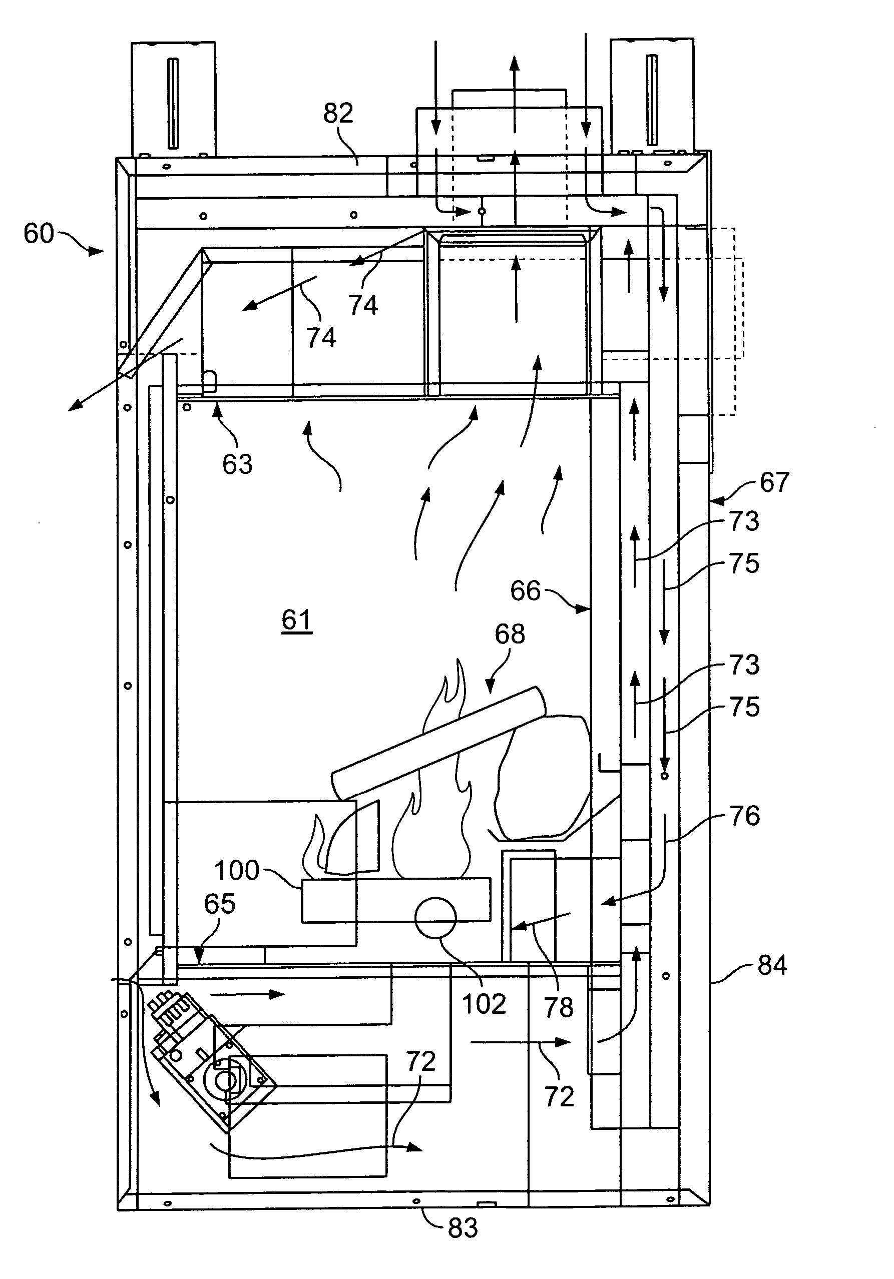
[0041]FIG. 1 illustrates a gas-fueled heating unit, which in a preferred embodiment is a fireplace in accordance with one embodiment of the present invention. Referring to FIG. 1, a gas heating unit 60 includes a combustion chamber 61 with sidewalls (not shown), a rear wall 66 and top and bottom walls 63 and 65. Simulated logs, e.g., ceramic gas logs 68 ...


PUM


Abstract

The present invention is directed to a heating unit, such as a fireplace, including an interior housing forming a combustion chamber. The housing includes a top wall, a rear wall and sidewalls defining an exterior housing about the combustion chamber. A burner assembly is positioned to provide combustion to the combustion chamber and a heat-activated shutter is provided in communication with the burner assembly for controlling flow of air into the burner assembly.

Description

[0001] This application claims benefit from U.S. Provisional Application No. 60 / 700,639, filed Jul. 19, 2005.FIELD OF THE INVENTION [0002] The present invention relates generally to fireplaces and similar devices. In particular, the present invention relates to an apparatus for a fireplace unit or the like that regulates primary airflow to a burner of a fireplace. More particularly, the present invention includes an air shutter assembly automatically responsive to heat for controlling airflow to a main burner and / or a secondary burner to a gas fireplace or similar heating / lighting unit. BACKGROUND OF THE INVENTION [0003] Fireplaces are desirable features in the home. However, devices that burn non-solid materials, such as gas, or that produce heat electrically have gradually replaced traditional wood or other solid fuel-burning fireplaces. Like, wood, the combustion of gas does provide real flames and heat, but requires a careful mixing of gas and air for optimal performance and a r...

Claims


Application Information

Patent Timeline
Patent Type & Authority Applications(United States)
IPC IPC(8): F24B1/18
CPCF24B1/1808
Inventor ALMASRI, RASHEDBEAL, THOMAS J.
Owner CFM
Why Eureka
Try Eureka