Control device for an internal combustion engine

Inactive Publication Date: 2005-08-04
TOYOTA JIDOSHA KK
View PDF4 Cites 3 Cited by
  • Summary
  • Abstract
  • Description
  • Claims
  • Application Information

AI Technical Summary

Benefits of technology

[0008] According to the present invention, there is provided a control device for an internal combustion engine which makes the engine speed, increased rapidly at the engine start, converge to a target engine speed by a feed-back retard control of an ignition time, characterized in that if the ignition time when the engine speed converges at the target engine speed is in the advance side than a target ignition time, the ignition time is retarded to the target ignition time and an amount of intake air is increased.
[0009] According to the above control device, if the ignition time when the engine speed converges at the target engine speed is on the advance side of the target ignition time, the ignition time is retarded at the target ignition time. Thus, the temperature of the exhaust gas increases sufficiently so that the catalytic device can be warmed up immediately. At this time, if nothing is done, the engine speed drops to less than the target engine speed. However, an amount of intake air is increased and thus the engine speed can be maintained at the target engine speed.

Problems solved by technology

At this case, in the above art, the ignition time is more advanced than the target ignition time so that the temperature of the exhaust gas does not increase sufficiently, and thus the catalytic device cannot be warmed up immediately.

Method used


Image

  • Control device for an internal combustion engine
  • Control device for an internal combustion engine
  • Control device for an internal combustion engine

Examples


Embodiment Construction

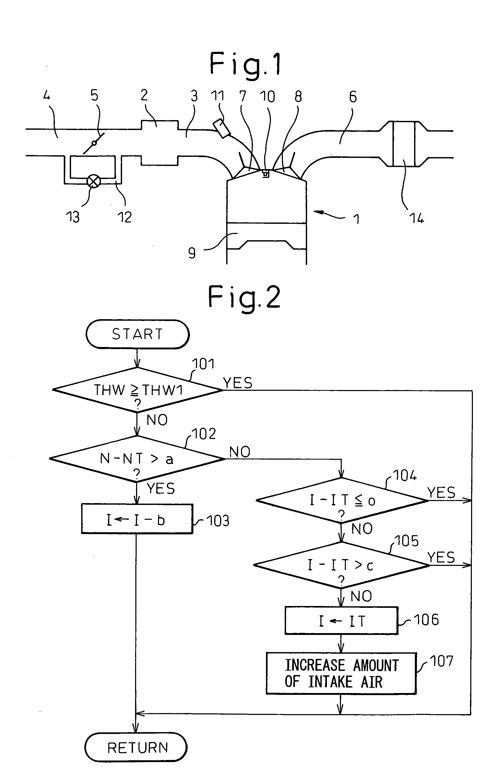
[0015]FIG. 1 is a schematic vertical sectional view of an engine provided with a control device according to the present invention. In FIG. 1, reference numeral 1 designates an engine body, and reference numeral 2 designates a surge-tank in common with each cylinder. Reference numeral 3 designates an intake port communicating the surge-tank 2 with each cylinder, and reference numeral 4 designates an intake passage upstream of the surge-tank 2. In the intake passage 4, a throttle valve 5 is arranged immediately upstream of the surge-tank 2. Reference numeral 6 designates an exhaust manifold communicating with each cylinder.

[0016] In the engine body 1, reference numeral 7 designates an intake valve, reference numeral 8 designates an exhaust valve, reference numeral 9 designates a piston, and reference numeral 10 designates an ignition plug. Reference numeral 11 designates a fuel injector arranged in each intake port 3. Reference numeral 12 designates a bypass passage connecting with ...


PUM


Abstract

A control device for an internal combustion engine, which makes the engine speed increased rapidly at the engine starting, converge to a target engine speed by a feed-back retard control of an ignition time, is disclosed. In the control device, if the ignition time when the engine speed converges at the target engine speed is in the advance side than a target ignition time, the ignition time is retarded to the target ignition time and an amount of intake air is increased.

Description

BACKGROUND OF THE INVENTION [0001] 1. Field of the Invention [0002] The present invention relates to a control device for an internal combustion engine. [0003] 2. Description of the Related Art [0004] In cold engine starting, it is desirable that a catalytic device arranged in the exhaust system is warmed up immediately to purify the exhaust gas soon after the engine starts. To make a catalytic device be warmed up immediately, it is suggested to make an engine speed increased rapidly at the engine starting converge at a target engine speed by retarding of an ignition time. (For example, refer to Japanese Unexamined Patent Publication Nos. 2003-254141 and 2001-90581.) [0005] In the above art, the ignition time is retarded so that the temperature of the exhaust gas increases to promote the warming-up of the catalytic device. Further, if the engine speed is still higher than the target engine speed when the ignition time has been retarded to the target ignition time, an amount of intak...

Claims


Application Information

Patent Timeline
IPC IPC(8): F02D31/00F02D37/02F02D41/06F02D43/00F02P5/15
CPCF02D31/005Y02T10/46F02P5/1508F02D37/02Y02T10/40
Inventor OI, YASUHIROYAGIHASHI, NOBUO
Owner TOYOTA JIDOSHA KK
Why Eureka
Try Eureka