
Waterproof slide fastener and apparatus for manufacturing the same

a technology of fasteners and slides, applied in the field of waterproof slide fasteners, can solve the problems of reducing waterproof performance, unable to guarantee the secureness of sliding operations, and the sliding resistance cannot be reduced so much, so as to improve the processing accuracy of the tape end nipping portion, improve the processing accuracy, and improve the waterproof performance

Active Publication Date: 2007-07-26
YKK CORP
View PDF3 Cites 4 Cited by
  • Summary
  • Abstract
  • Description
  • Claims
  • Application Information

AI Technical Summary

Benefits of technology

The present invention provides a waterproof slide fastener that can intensify fixing strength and waterproof performance between a fastener stringer and a fastener element, allowing for a smooth sliding operation of a slider. The waterproof slide fastener is easy to manufacture and can be made with a manufacturing apparatus. The technical effects of the invention include improved strength and waterproof performance of the fastener, as well as smoother operation of the slider.

Problems solved by technology

Even if a component of force applied obliquely downward to the fastener element decreases when the slider is slid, in case of an ordinary slider, this only can meet an increase in sliding resistance accompanied by an increase in the sliding area and thus, there is no guarantee that a smooth sliding operation is secured.
Therefore, the upper and lower opposing faces of the flanges may make a sliding contact with the fastener tape, so that the synthetic resin layers on the front and rear faces of the fastener tape may be flawed by rubbing, thereby possibly leading to reduction in waterproof performance.
However, the sliding resistance can not be reduced so much because its sliding area is large.

Method used


Image

  • Waterproof slide fastener and apparatus for manufacturing the same
  • Waterproof slide fastener and apparatus for manufacturing the same
  • Waterproof slide fastener and apparatus for manufacturing the same

Examples


first embodiment

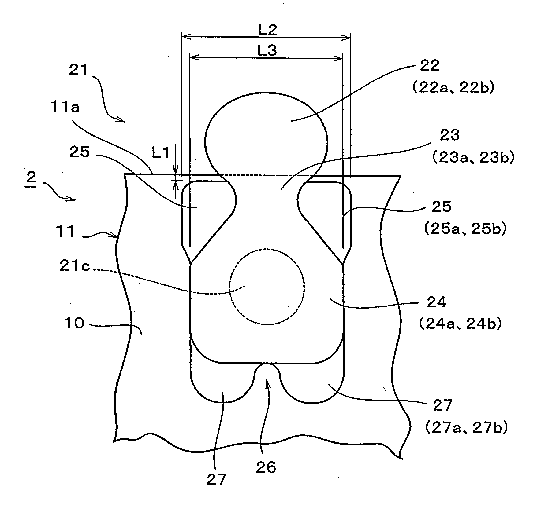
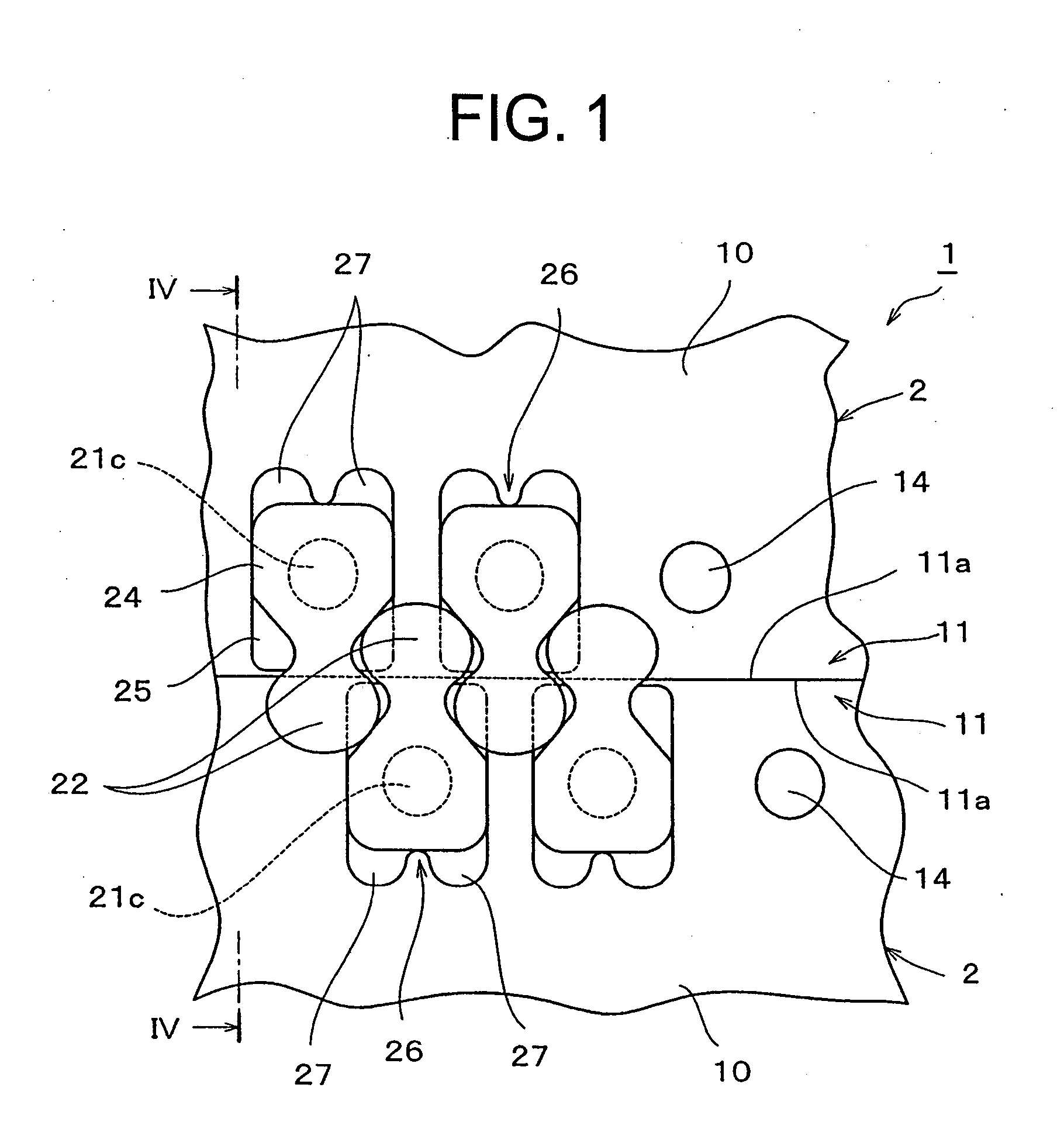
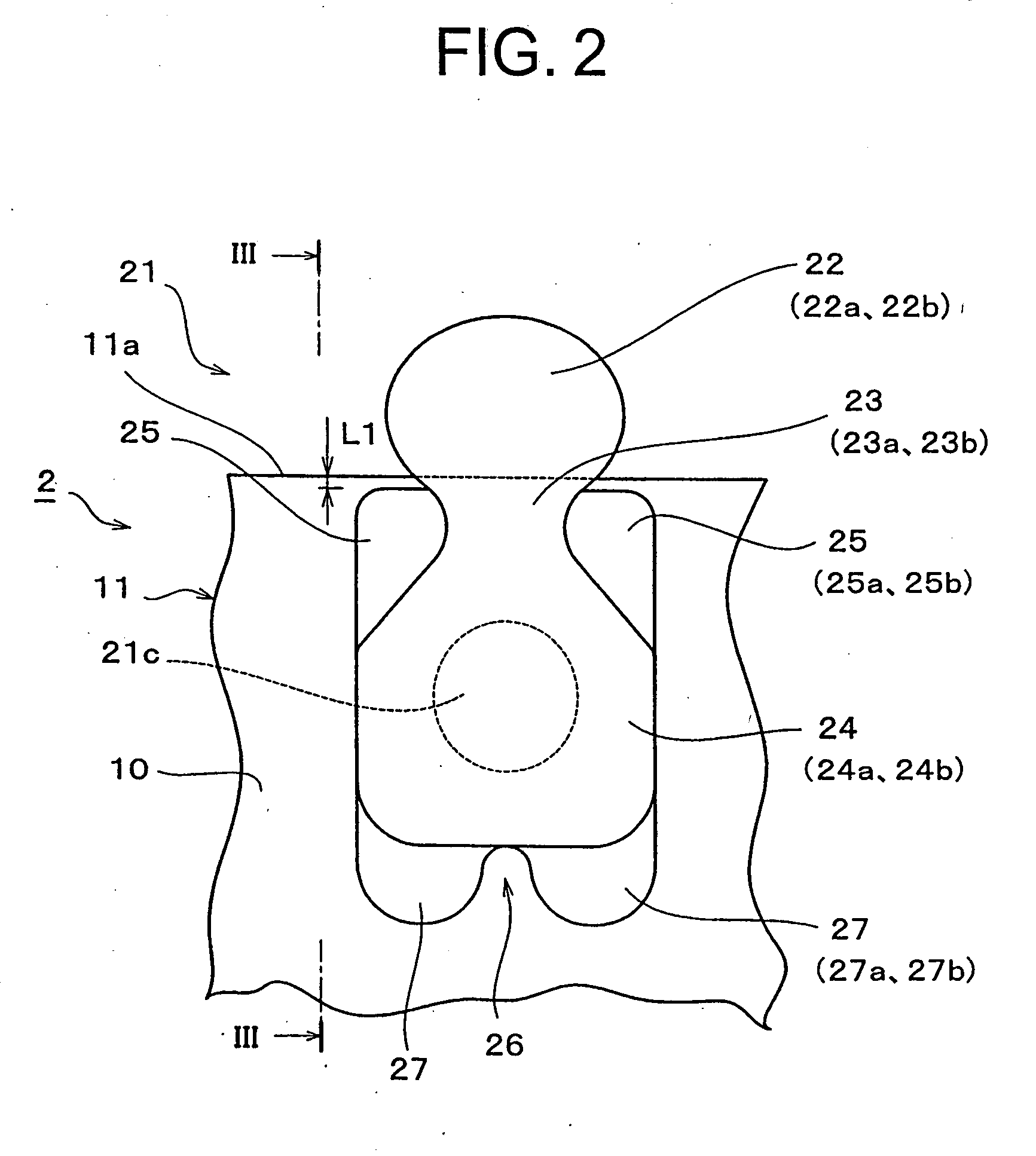
[0040]FIG. 1 is a plan view showing part of a waterproof slide fastener according to a first embodiment of the present invention. FIG. 2 is a plan view of a fastener element having a feature portion of the present invention applied to the same slide fastener. FIG. 3 is a side view of the same element. Although the present invention naturally includes an airtight slide fastener, the waterproof slide fastener is exemplified for this embodiment.

[0041] In a slide fastener 1 of this embodiment, a plurality of fastener elements 21 are formed integrally with a coupling interval with respect to each mating fastener element 21 along an element mounting edge portion 11 which is a side edge portion of a waterproof fastener tape 10, so as to form a fastener element row. Further, the slide fastener 1 is provided with synthetic resin made or metallic slider and top and bottom end stops having an ordinary structure, although not shown in the figures.

[0042] The waterproof fastener tape 10 is prod...

second embodiment

[0055]FIGS. 6 and 7 show a second embodiment of the present invention.

[0056] This embodiment is different from the first embodiment only in that an entire shoulder width L2 between right and left ends of the right and left shoulder portions 25 is set larger than a body width L3 of the body portion 24. According to this embodiment, the conventional single fin piece may be used instead of the two leg portions 27, 27. Because the entire shoulder width L2 is set larger than the body width L3, a surface area of the shoulder portion 25 increases, so that a contact area between a surface of the shoulder portion 25 and an inside face of the coupling head 22 increases, thereby intensifying waterproofness.

[0057]FIGS. 8 and 9 show modifications of the shoulder portion 25. According to these modifications, volumes of the upper and lower half portion molding cavities 34d, 35d of the shoulder portion 25 to be formed in the injection molding die 30 increase by an amount corresponding to an incre...

third embodiment

[0059] FIGS. 11 to 15 show a third embodiment of the present invention. According to this embodiment, a pair of protrusions 28 are provided in a center of each of opposing faces of respective half portions 22a, 22b of the coupling heads 22 extending outward in parallel from the element mounting edge portion 11 of the fastener tape 10 with the gap, the protrusions being started from a coupling head side end of each of the upper and lower half portions 23a, 23b of the neck portion 23 and extending toward a vertex of each of the half portions 22a, 22b of the coupling heads 22 up to halfway thereof. A width of each protrusion 28 is set to such a dimension which allows both the right and left side faces of the protrusion 28 of one coupling head 22 to be located between adjoining shoulder portions 25, 25 of a mating fastener elements when respective fastener elements engage each other. The width, an extension length and a shape of the protrusion 28 are determined under a condition in whic...


PUM

PropertyMeasurementUnit
lengthaaaaaaaaaa
pressureaaaaaaaaaa
densityaaaaaaaaaa

Abstract

The invention provides a waterproof slide fastener and a manufacturing apparatus thereof, wherein each fastener element has a coupling head, a neck portion, a body portion, and leg portions which are continuously fused and integrated, a terminal end is projected from a gap between upper / lower half portions of the coupling head, upper / lower flanges of a slider make a sliding contact with a surface of each of upper / lower half portions of each leg portion, each half portion of the leg portion extending from the body portion via a crotch portion and guiding the flanges, two or more leg portions are disposed with a predetermined interval in a sliding direction, an entire shoulder width of a shoulder portion is larger than a body width of the body portion if it is provided, thereby intensifying fixing strength between a fastener tape and fastener elements and waterproofness, and allowing a smooth sliding of a slider.

Description

BACKGROUND OF THE INVENTION [0001] 1. Field of the Invention [0002] The present invention relates to a waterproof slide fastener in which a plurality of synthetic resin made fastener elements are formed by injection molding on both front and rear faces of one edge portion of a waterproof fastener tape including a waterproof layer made of elastomer resin on a belt-like core material formed by weaving or knitting, and an apparatus for manufacturing the same. [0003] 2. Description of Related Art [0004] This kind of slide fastener has a waterproofing structure in which with the fastener tape woven or knitted with fibers as a belt-like core material, both front and rear faces of the core material are covered with an elastomer material such as natural rubber or synthetic rubber, and fastener elements of synthetic resin are formed integrally by injection molding along one side edge of this fastener tape such that each of them strides over the front and rear faces. Usually, an element mount...

Claims


Application Information

Patent Timeline
Patent Type & Authority Applications(United States)
IPC IPC(8): A44B19/32A44B19/04A44B19/08A44B19/40B29D5/02
CPCA44B19/08A44B19/32A44B19/403Y10S425/814Y10T24/2514Y10T24/2557Y10T24/25B29D5/02E04H17/20E04H17/1413E04H17/1469E04H17/143E04H17/1447
Inventor KUSAYAMA, MASAHIROYUKI, KENJITANAKA, RYO
Owner YKK CORP
Learn More