
Method of synthesizing silicon wires

a technology of silicon wires and wires, which is applied in the direction of crystal growth process, polycrystalline material growth, chemistry apparatus and processes, etc., can solve the problems of increasing environmental control costs associated with it, limited use of silicon wires, and difficult catalytical effect of silicon wires, and introducing cheaper metals, fe and ni selection,

Active Publication Date: 2007-07-19
TSINGHUA UNIV +1
View PDF3 Cites 38 Cited by
  • Summary
  • Abstract
  • Description
  • Claims
  • Application Information

AI Technical Summary

Benefits of technology

[0031]In the present method, the conventional Fe or Ni is replaced with Cu as the catalyst material used to synthesize silicon wires. Thus, the reactive temperature of synthesis of silicon wires is lower, thereby decreasing the requirement for the thermal performance of the high temperature reactive device. Furthermore, copper is a cheap metal that is readily processed. Therefore, the synthesizing cost of silicon wires is decreased. Moreover, many semiconductor elements employ conductive traces that are made from Cu. As such, given the known compatibility of copper with silicon-based semiconductor elements, the semiconductor elements are unlikely to be adversely polluted by the Cu catalysts, thereby ensuring the performance of the semiconductor elements.

Problems solved by technology

Although Au is a usual catalyst for silicon wires by the VLS method, the use thereof is limited by its expense.
Furthermore, in the VLS method employing Au as a catalyst, poisonous and / or noxious matter is prone to be formed in the process, thereby forming pollutants that have to captured and, thus, increasing the environmental control costs associated therewith.
The introduction of cheaper metals, selected from Fe and Ni, to catalyze the silicon wires has proven difficult over at least two issues.
On the one hand, in the VLS method employing Fe or Ni as catalysts, high synthesizing temperature (i.e., above 1000° C.) is needed, thereby increasing the cost of the fabrication.
On the other hand, the catalysts of Fe or Ni are prone to render unwanted impurities within semiconductor elements, thereby decreasing the performance thereof.

Method used


Image

  • Method of synthesizing silicon wires
  • Method of synthesizing silicon wires
  • Method of synthesizing silicon wires

Examples


Embodiment Construction

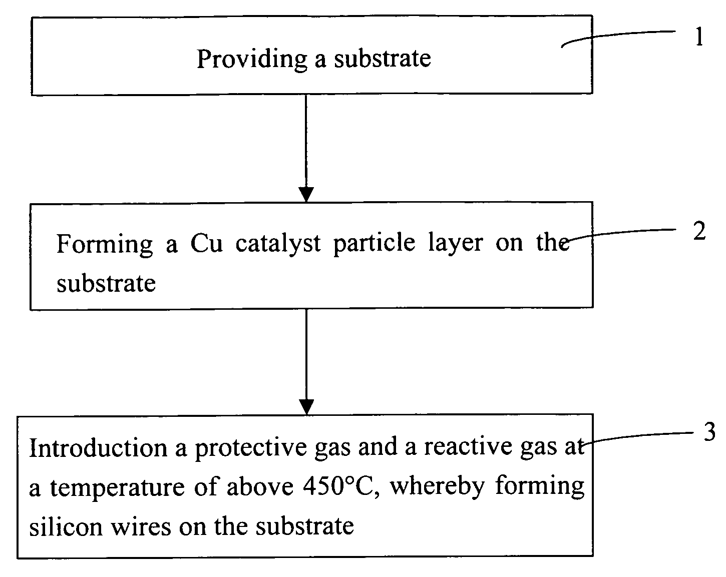
[0023]Reference will now be made to the drawings to describe the synthesizing of silicon wires employing Cu as catalyst according to the present method, in detail.

[0024]Referring to FIG. 1, a substrate is firstly provided. The substrate is advantageously made from a non-metallic material (e.g. silicon, silicon dioxide, quartz, glass, etc).

[0025]Next, a Cu catalyst particle layer is formed on a top surface of the substrate. According to the sizes of the needed silicon wires, the Cu catalyst particles can be selected from one of micro-scale Cu particles, submicro-scale Cu particles, and nano-scale particles, respectively, as the particle size (i.e., diameter) will directly impact the diameter of the wire produced therewith (i.e., a nano-sized copper particle is used to catalyze the growth of a nano-sized diameter silicon wire).

[0026]A method of the formation of the Cu catalyst layer generally includes the steps of: (a) depositing a Cu layer on the top surface of the substrate by a phy...


PUM

PropertyMeasurementUnit
pressureaaaaaaaaaa
temperatureaaaaaaaaaa

Abstract

A method of synthesizing silicon wires generally includes the steps of: providing a substrate; forming a copper catalyst particle layer on a top surface of the substrate; heating the reactive device at a temperature of above 450° C. in a flowing protective gas; and introducing a mixture of a protective gas and a silicon-based reactive gas at a temperature of above 450° C. at a pressure of below 700 Torr, thereby forming the silicon wires on the substrate.

Description

BACKGROUND[0001]1. Technical Field[0002]The invention relates generally to methods of synthesizing silicon wires and, particularly, to a method of synthesizing silicon wires that employs metallic catalysts.[0003]2. Discussion of Related Art[0004]Since silicon is one of the most favored materials in the semiconductor industry and as it has been used in the IC industry for many years, much attention has already been paid to the research and synthesis of silicon wires. As early as in 1964, micrometer-scaled silicon whiskers grown on silicon substrates were synthesized by a Vapor-liquid-solid (VLS) method. Nowadays, VLS method is an important way to synthesize silicon wires. In this method, metals, generally selected from gold (Au), nickel (Ni) and iron (Fe), are employed as catalysts.[0005]Although Au is a usual catalyst for silicon wires by the VLS method, the use thereof is limited by its expense. Furthermore, in the VLS method employing Au as a catalyst, poisonous and / or noxious mat...

Claims


Application Information

Patent Timeline
Patent Type & Authority Applications(United States)
IPC IPC(8): H01L21/84
CPCC30B11/12C30B29/62C30B29/06Y10S977/769Y10S977/762
Inventor YAO, YUANXU, LI-GUOFAN, SHOU-SHAN
Owner TSINGHUA UNIV
Learn More