
Thin air processing device for heat ventilation air conditioning system

Inactive Publication Date: 2007-07-19
INDAL DESIGN LAB
View PDF7 Cites 32 Cited by
  • Summary
  • Abstract
  • Description
  • Claims
  • Application Information

AI Technical Summary

Problems solved by technology

Axial fans are rarely used as air moving devices because they do not create enough static pressure required at the required airflow.
Electric motors for typical crossflow blowers are located adjacent to the impellers and a drive is achieved by belt or other means, because when the electric motor is placed inside the impeller it destroys the internal aerodynamic structure of the crossflow blower thus dramatically decreasing performance characteristics.
But, known designs do not allow a thin air processing device with the crossflow blower for such wall-mounted air movement systems.
Such solutions are thicker than desired, and neither satisfy the market.
The main problem of all known air processing devices is that they cannot resolve the contradiction between the high performance that requires a relatively big impeller diameter on the one hand and a small thickness of the whole device on the other hand.

Method used


Image

  • Thin air processing device for heat ventilation air conditioning system
  • Thin air processing device for heat ventilation air conditioning system
  • Thin air processing device for heat ventilation air conditioning system

Examples


second embodiment

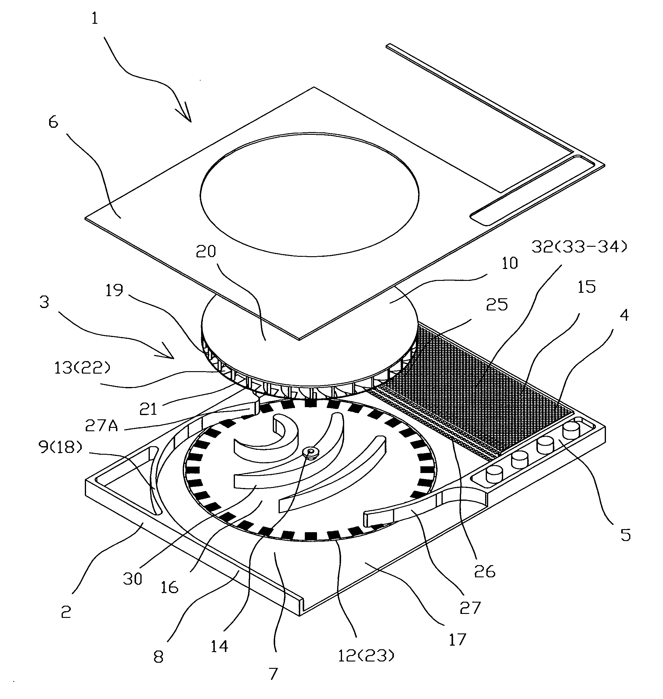
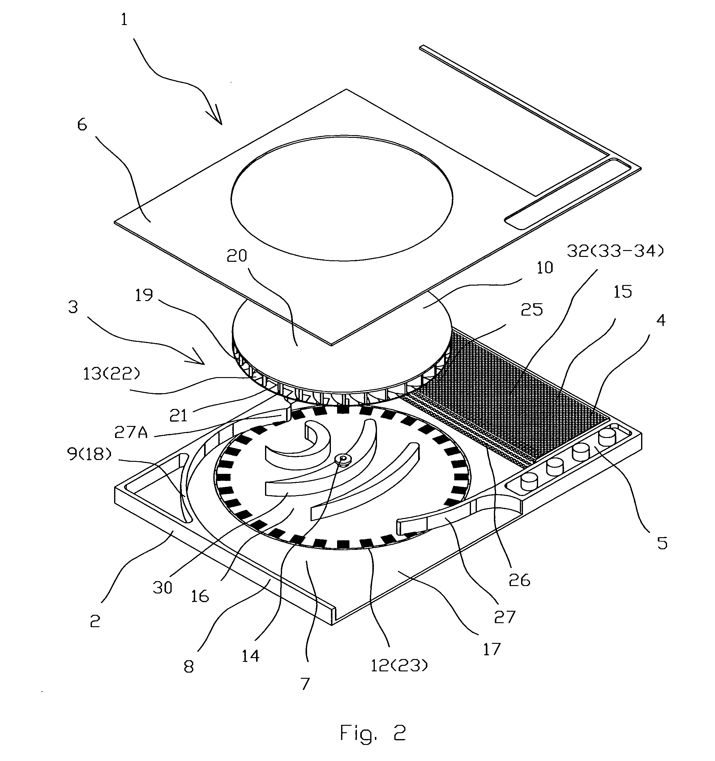
[0035]According to the present invention the flat stator 12 integrated with the cover plate 6 while the magnetic means 22 integrated with the backplate 20.

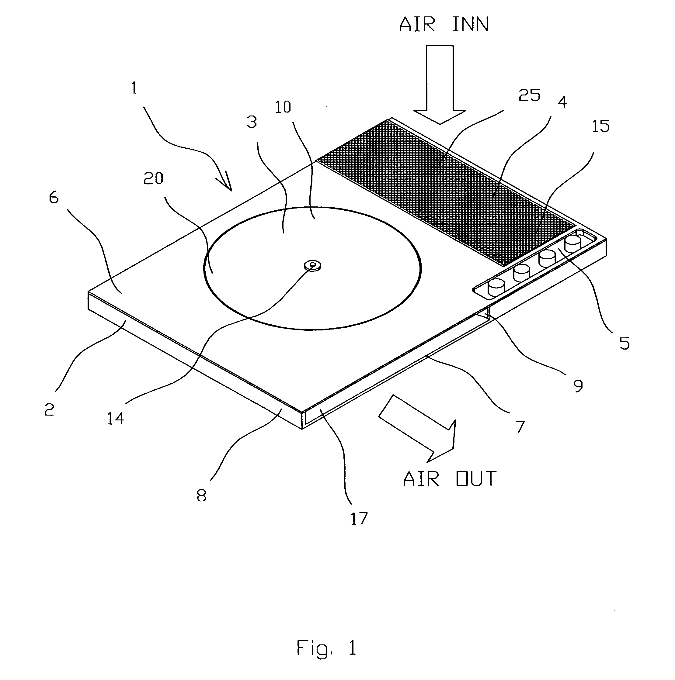
[0036]There are two design options according to both embodiments. The first design option (FIGS. 1-7) realizes an aerodynamic scheme when ambient air goes to the intake opening 25 of the air processing unit 4 in direction perpendicular to the cover plate 6, while the second design option (FIGS. 8-9) realizes the aerodynamic scheme when ambient air goes to the corresponding intake opening 25 from side in direction parallel to the cover plate 6.

third embodiment

[0037]According to the present invention (FIGS. 11-12A) at least one guide vane 30 integrated with the cover plate 7. Ambient air in this case goes to the intake opening 25 from side in direction parallel to the cover plate 6. Unlike the previous embodiments the backplate 20 located closer to the base 7 than shroud 21. The detailed mutual layout of components of the electric drive 11 is shown on FIGS. 12 and 12A. The coils 23 are integrated with the base 7 while magnetic means 22 are integrated with the backplate 20 by supporting ring 24 and retaining ring 35. The variant design shown on FIG. 12A differs from design shown on FIG. 12 by the conical upper surface 36 of the backplate 20 and may be used in extremely slim design of air processing device 1 according to the present invention.

[0038]According to all embodiments and variant designs the air processing unit 4 may be made like air purifier 32 and / or humidifier 34 and / or may comprises the temperature regulating means 33.

[0039]The...


PUM


Abstract

A thin air processing device suitable for wall mounting comprises a housing and located inside a crossflow blower, an air processing unit and a controller unit. The housing comprises a cover plate, a base and side parts. The blower comprises a casing, an impeller, an electric drive with a flat stator and a magnetized rotor, and an axle fixed perpendicularly to the base. The casing comprises an inlet, a central part and an outlet and integrated with the housing thus a volute shape of the casing formed by side parts. The impeller comprises circumferential arrayed magnetic means thus serving as the magnetized rotor. The flat stator comprises circumferential arrayed coils with magnetic axes coincide with a plane of the flat stator and integrated with the housing. The air processing unit located at the inlet of the casing and comprises an intake and an outtake openings.

Description

CROSS REFERENCE TO RELATED APPLICATIONS[0001]The present application claims the benefit of priority of U.S. Provisional Patent Application No. 60 / 759,949 filed Jan. 19, 2006 for Edward Lopatinsky et al. the entire content of which is incorporated herein by reference.FIELD OF THE INVENTION[0002]The present invention relates generally to heat ventilation air conditioning (HVAC) systems for moving air, and / or regulating the temperature, humidity and quality of indoor air. More particularly, the present invention relates to air processing devices such as ventilators including heat ventilators, coolers, air conditioners and air purifiers. The present invention is particularly, but not exclusively, useful for systems that are mounted on the wall and became a part of room décor; therefore, thickness of the system is a critical factor.BACKGROUND OF THE INVENTION[0003]Regulation of the temperature, humidity and indoor air quality is an important consideration during the design of HVAC system...

Claims


Application Information

Patent Timeline
IPC IPC(8): F04B17/00
CPCF04D17/04
Inventor LOPATINSKY, EDWARDFEDOSEYEV, LEVSCHAEFER, DANIEL
Owner INDAL DESIGN LAB
Learn More