Planar light source device
a light source device and planar technology, applied in the direction of lighting and heating apparatus, mechanical equipment, instruments, etc., can solve the problems of increasing the number of necessary parts, reducing reliability, and large frame or thickness of the planar light source device, so as to reduce uneven luminance and efficiently disperse heat
- Summary
- Abstract
- Description
- Claims
- Application Information
AI Technical Summary
Benefits of technology
Problems solved by technology
Method used
Image
Examples
embodiment 1
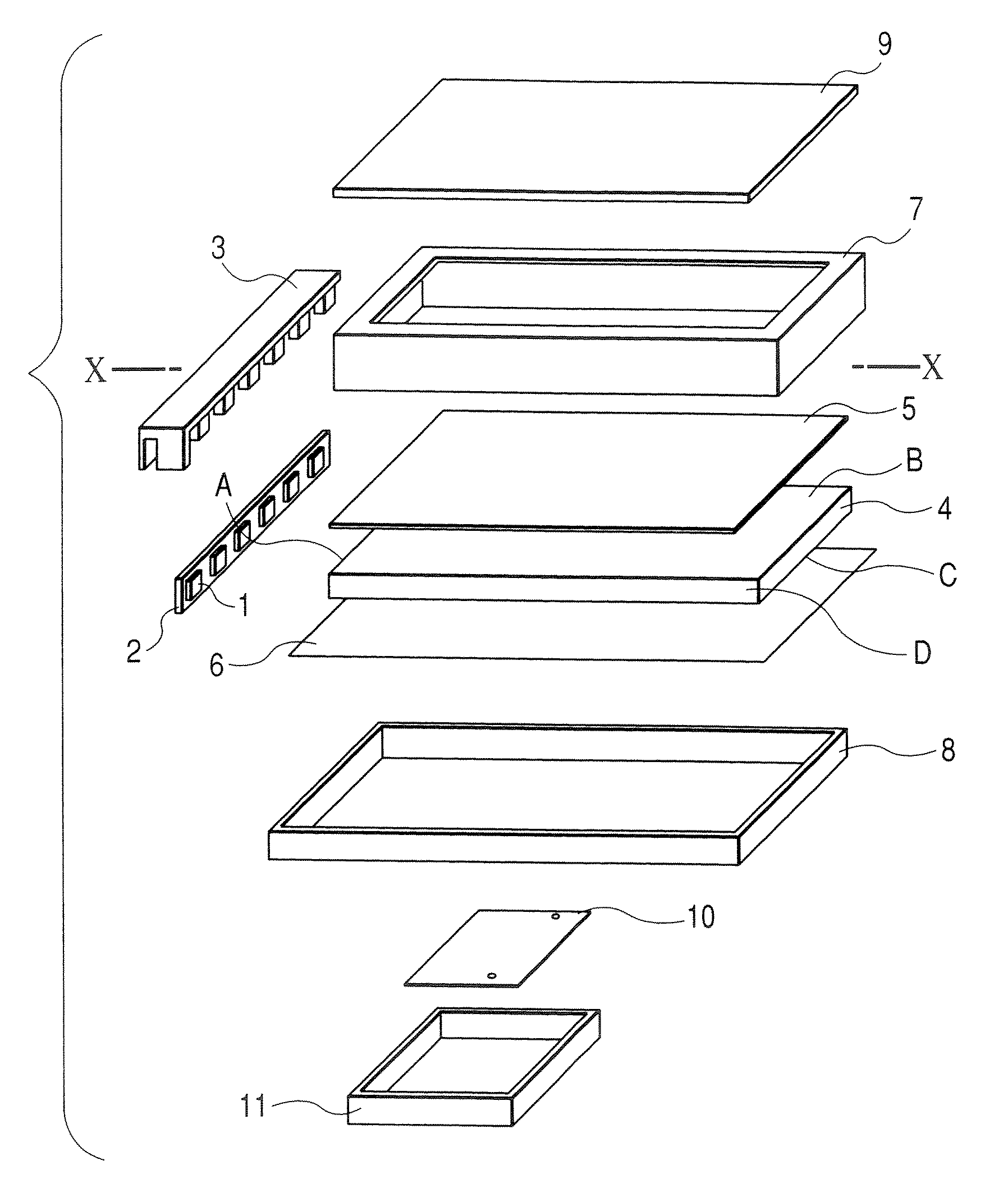
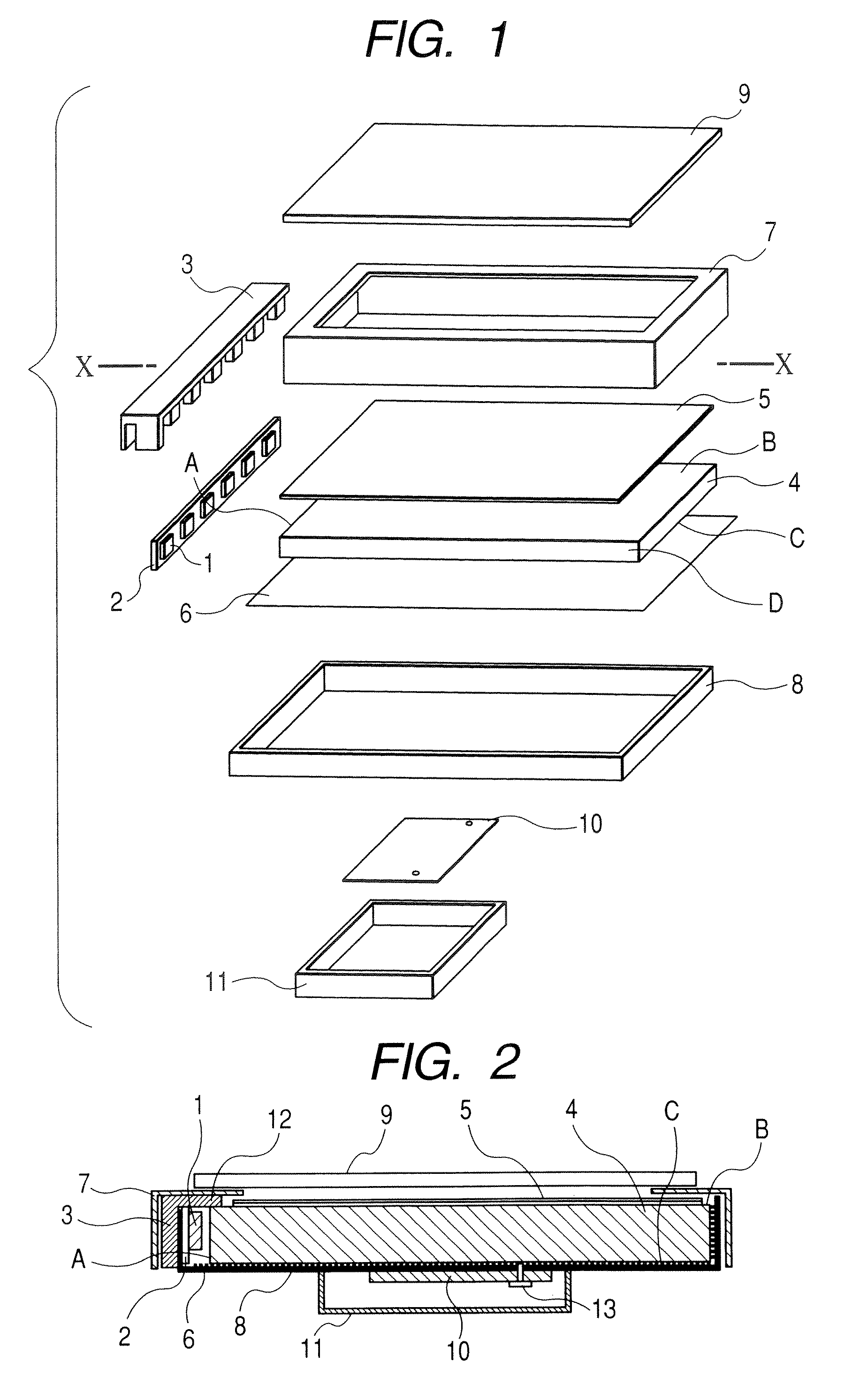
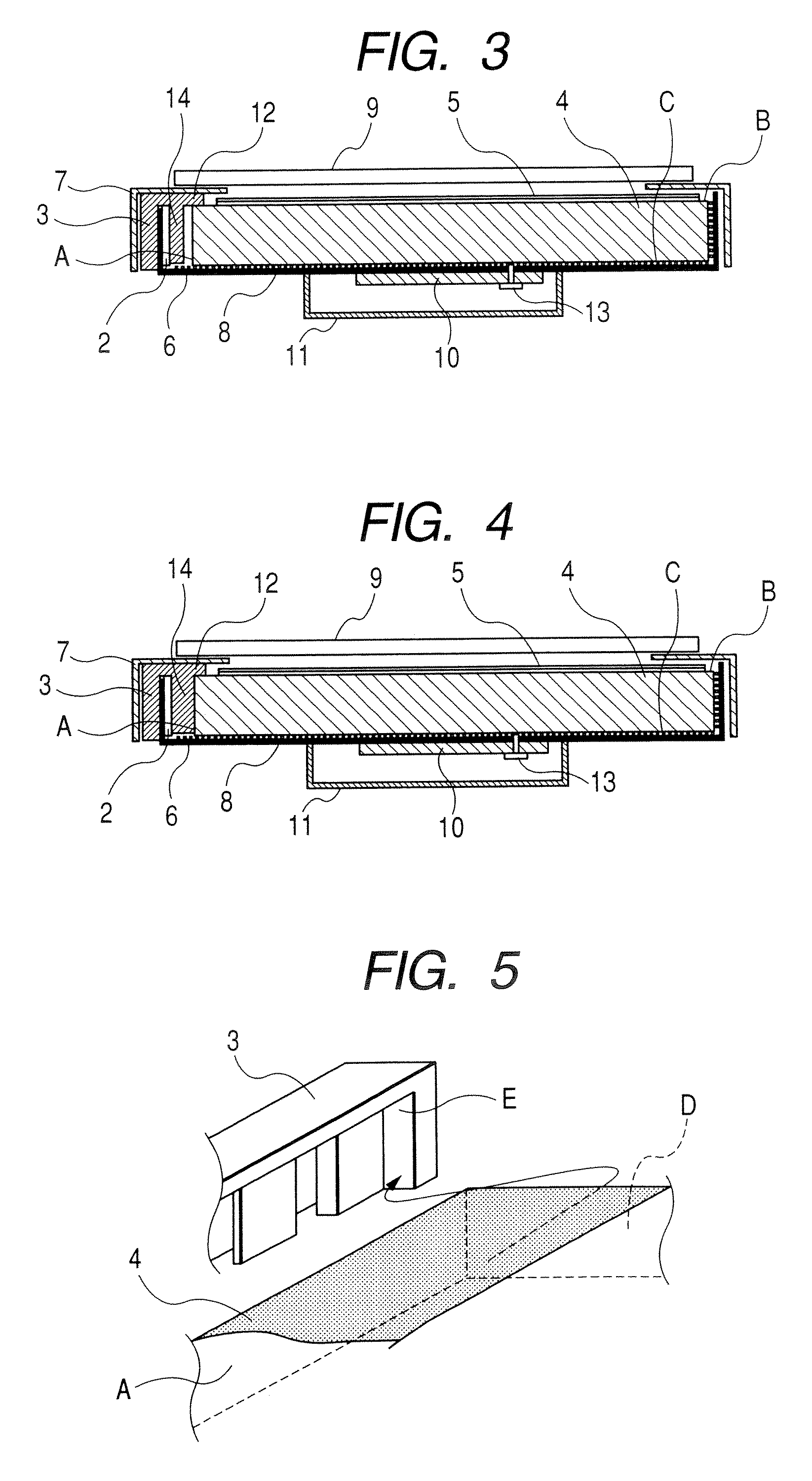
[0020]Embodiment 1 of the invention will be described referring to FIGS. 1 to 5. FIG. 1 is an exploded perspective view illustrating a planar light source device according to Embodiment 1. FIGS. 2 to 4 are cross-sectional views of a display device along the X-X direction assembled and completed from parts shown in the exploded view of FIG. 1. FIG. 5 is an enlarged perspective view of the display device.
[0021]Referring to FIG. 1, a plurality of point light sources 1 such as LEDs are arranged almost in a row while being installed on a light source substrate 2. The light source substrate 2 is supported by a resin frame 3 (the supporting method will be described later). The point light sources 1 are arranged in close proximity to one side of a light guide plate 4. A side A to which light from a light source is incident is hereinafter referred to as a light incident surface. Light from point light sources that enter the light incident surface A is emitted from the light outgoing surface ...
embodiment 2
[0039]Embodiment 2 of the invention will be described referring to FIG. 6. FIG. 6 is cross-sectional view of a display device along the X-X direction assembled and completed from parts shown in the exploded view of FIG. 1 according to Embodiment 1. In FIG. 6, same components as those in FIGS. 1 to 5 are given the same signs.
[0040]FIG. 6 shows a planar light source device according to Embodiment 2. Differences from Embodiment 1 will be described. FIG. 6 is a cross-sectional view of the area between adjacent point light sources of the planar light source device according to Embodiment 2. The cross sectional configuration of a point light source and the proximity to both ends of a resin frame of the planar light source device shown in FIG. 6 is the same as that in Embodiment 1. In FIG. 6, Embodiment 2 is different from Embodiment 1 in that a projection 12 of the resin frame 3 coming into contact with the light outgoing surface B of the light guide plate 4 between point light sources 1 ...
embodiment 3
[0043]Embodiment 3 of the invention will be described referring to FIG. 7. FIG. 7 shows cross-sectional view of a display device along the X-X direction assembled and completed from parts shown in the exploded view of FIG. 1 according to Embodiment 1. In FIG. 7, same components as those in FIGS. 1 to 6 are given the same signs.
[0044]FIG. 7 illustrates a planar light source device according to Embodiment 3. Differences from Embodiments 1 and 2 will be described. FIG. 7 is a cross-sectional view of the portion between adjacent point light sources of the planar light source device according to Embodiment 3. The cross sectional configuration of a point light source and the proximity to both ends of a resin frame of the planar light source device shown in FIG. 7 is the same as that in Embodiment 1. In FIG. 7, Embodiment 3 is different from Embodiments 1 and 2 in that a dome-shaped part 16 made of solder is provided on a light source substrate 2 at each area between adjacent point light s...
PUM
 Abstract
Description
Claims
Application Information
 - R&D
- Intellectual Property
- Life Sciences
- Materials
- Tech Scout
- Unparalleled Data Quality
- Higher Quality Content
- 60% Fewer Hallucinations
Browse by: Latest US Patents, China's latest patents, Technical Efficacy Thesaurus, Application Domain, Technology Topic, Popular Technical Reports.
© 2025 PatSnap. All rights reserved.Legal|Privacy policy|Modern Slavery Act Transparency Statement|Sitemap|About US| Contact US: help@patsnap.com


