
Operating mode switch for setting at least one operating mode in a hand-held power tool

Inactive Publication Date: 2007-07-19
ROBERT BOSCH GMBH
View PDF4 Cites 8 Cited by
  • Summary
  • Abstract
  • Description
  • Claims
  • Application Information

AI Technical Summary

Benefits of technology

[0004] Accordingly, it is an object of the present invention to provide an operating mode switch for setting at least one operating mode in a hand-held power tool, which eliminates the disadvantages of the prior art.
[0006] When the operating mode switch is designed in accordance with the present invention it has the advantage that the locking device ensures the functionality of the hand-held power tool in the selected operating mode—which is activated using the setting ring—despite vibrations, handling errors, and other external influences, e.g., accidental rotation of the setting ring caused by circumstances in the operating environment. This is particularly significant for the “impact drilling” mode, since considerable impact-related vibrations are produced in this case, which cause the unsecured setting ring to rotate, thereby resulting in malfunction.
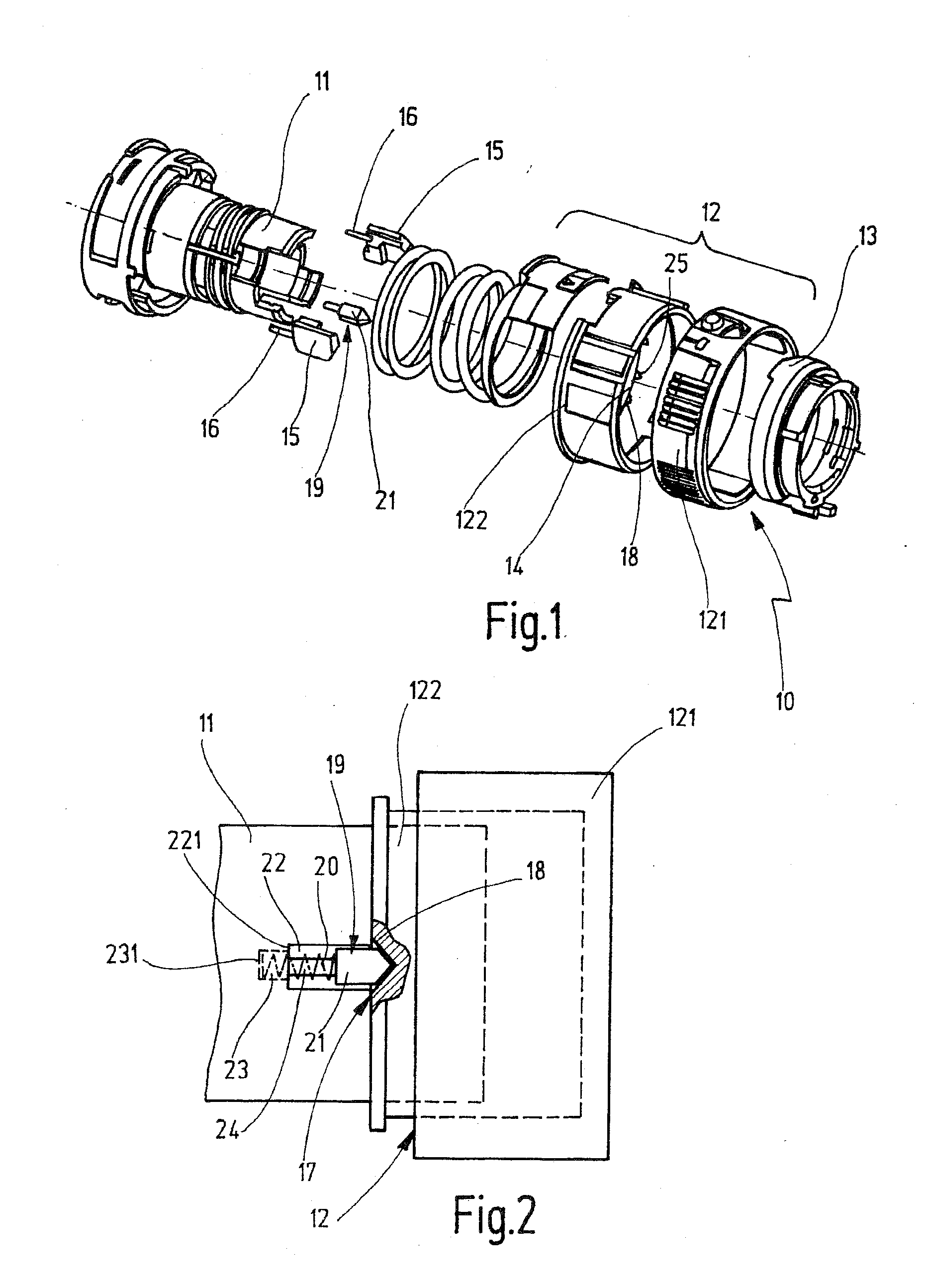
[0007] According to an advantageous embodiment of the present invention, the locking device includes at least one recess located in a sliding track formed in the adjustment ring, and an axially displaceable, non-rotatably held locking element designed to at least partially engage in the recess in a form-fit manner and which bears against the sliding track with an axially directed spring force. This design of the locking device is simple and robust, and it ensures reliable locking quality.
[0008] According to an advantageous embodiment of the present invention, the locking element is designed as a sliding wedge which is acted upon by a compression spring and includes a wedge angle pointing toward the sliding track. This recess is triangular, with a triangular angle corresponding to the wedge angle. By adjusting the wedge angle of the sliding wedge and adapting the triangular angle of the triangular recess accordingly, it is possible to adapt the manual force required to disengage the locking device to the customer's preference and to attain an optimum between locking quality and ease of use.

Problems solved by technology

This is particularly significant for the “impact drilling” mode, since considerable impact-related vibrations are produced in this case, which cause the unsecured setting ring to rotate, thereby resulting in malfunction.

Method used


Image

  • Operating mode switch for setting at least one operating mode in a hand-held power tool
  • Operating mode switch for setting at least one operating mode in a hand-held power tool

Examples


Embodiment Construction

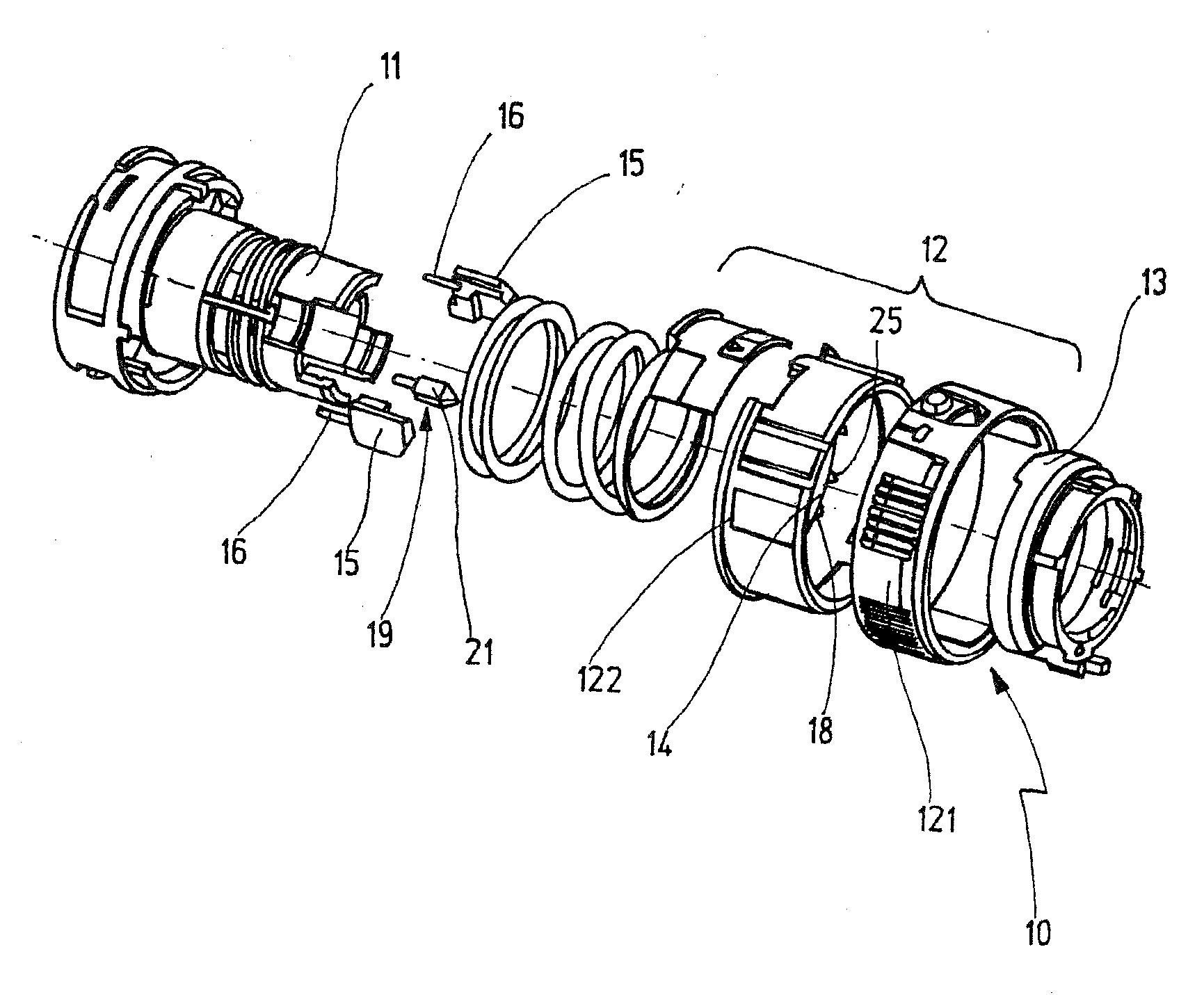
[0012] With the hand-held power tool shown in an exploded view, in sections, in FIG. 1, it is possible to switch to three different operating modes, i.e., the “impact drilling on / off” mode, the “drill” mode, and the “screw” mode, using an operating mode switch composed of two adjustment rings. In the “screw” mode, it is possible to preselect various starting torques. If this torque is exceeded, a safety clutch is activated, and the screwing tool cannot be driven.

[0013] The section of the hand-held power tool shown in FIG. 1 shows a guide sleeve 11 which is fixedly connected with the front region of a machine housing (not shown here) which accommodates an electric motor and a gearbox. A tool spindle (not shown here) is rotatably supported in guide sleeve 11, and operating mode switch 10 is located on guide sleeve 11. Operating mode switch 10 includes a setting ring for the “drill” and “screw” modes—and only one threaded ring 13 is shown—and a setting ring 12 with which the “impact d...


PUM


Abstract

An operating mode switch for setting at least one operating mode in a hand-held power tool, comprising an adjustment ring rotatable manually around its axis and movable into at least one rotational position which activates an operating mode, and a locking device controlled by the adjustment ring and engaging in the adjustment ring, the locking device being configured such that in the at least one rotational position of the adjustment ring it automatically falls into a locking position which locks the adjustment ring in position, while the engagement ring is engageable from the at least one rotational position by manually rotating the adjustment ring.

Description

CROSS-REFERENCE TO A RELATED APPLICATION [0001] The invention described and claimed hereinbelow is also described in German Patent Application DE 102005059182.5 filed on Dec. 12, 2005. This German Patent Application, whose subject matter is incorporated here by reference, provides the basis for a claim of priority of invention under 35 U.S.C. 119(a)-(d). BACKGROUND OF THE INVENTION [0002] The present invention is based on an operating mode switch for setting at least one operating mode in a hand-held power tool, in particular for selectively turning the “impact drilling” mode on or off in an impact drill. [0003] With a known impact drill with an operating mode switch for selecting several operating modes (DE 100 06 641 A1), the operating mode switch includes two adjustment or switching rings which are located next to each other on the machine housing and are designed such that one switching ring, in two consecutive setting positions, selects the “impact drilling on / off” mode, and th...

Claims


Application Information

Patent Timeline
IPC IPC(8): E02D7/02
CPCB25D16/006H01H9/20B25D2216/0038B25D2216/0023
Inventor AEBERHARD, BRUNOBUEHLMANN, FELIX
Owner ROBERT BOSCH GMBH
Learn More