
Bone conduction device and tympanum thereof

Active Publication Date: 2007-07-12
TEMCO JAPAN
View PDF5 Cites 5 Cited by
  • Summary
  • Abstract
  • Description
  • Claims
  • Application Information

AI Technical Summary

Benefits of technology

[0017] The bone conduction device of the present invention assumes a longitudinally elongated shape as a whole. Since a width of a shorter side of the device depends on a shorter width of the voice coil, it is possible to restrict a width of a shorter side of the speaker unit. Due to this, the bone conduction device of the present invention is best adapted to the use in a cellular phone and the like which is provided with a large display screen together with an available laterally elongated narrow installation space. In this case, any dead space is not produced in the cellular phone and the like when the bone conduction device of the present invention is installed therein. Further, as the effect of the present invention, it is possible to obtain a sufficient amount of output power of the device in the use of a cellular phone.
[0018] Further, the bone conduction speaker and its tympanum both according to the present invention are simple in construction. In addition, it is possible for the tympanum to be improved in compliance. Still further, the tympanum is capable of being mounted on the yoke by laser welding in an easy manner. Consequently, the bone conduction device of the present invention is easy in production and sufficiently strong in physical strength. Due to this, particularly, in case of the invention described in claim 4, the device defined in the claim may enjoy its sufficiently large impact resistance.

Problems solved by technology

Under such circumstances, since a need exists in the latest cellular phone for increasing in area size a display screen in a front surface of the cellular phone as large as possible, a space available for installation of a speaker in the cellular phone is limited only to a laterally elongated space positioned over the display screen.
This leads to a shortage in output power of the bone conduction speaker.
In this case, however, there is a fear that a considerable loss in space occurs in the cellular phone.

Method used


Image

  • Bone conduction device and tympanum thereof
  • Bone conduction device and tympanum thereof
  • Bone conduction device and tympanum thereof

Examples


Embodiment Construction

[0019] Preferred embodiments for carrying out the present invention will be described with reference to the accompanying drawings. In the following description, a bone conduction speaker used in a bone conduction device will be described. Although the following description will be made with respect to the bone conduction speaker used in the bone conduction device, it is also possible to apply substantially the same description as that of the bone conduction speaker to a bone conduction microphone. Consequently, a description of such a bone conduction microphone will be omitted.

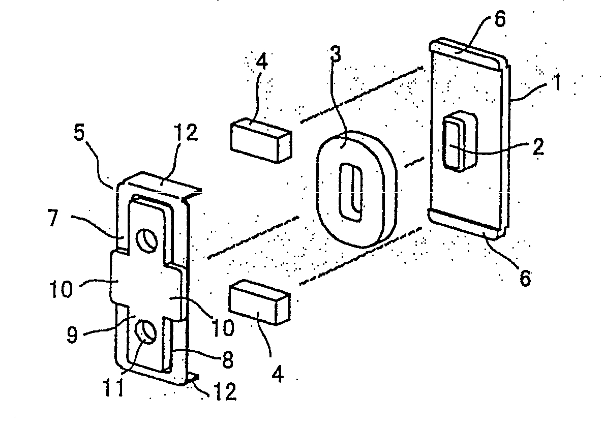
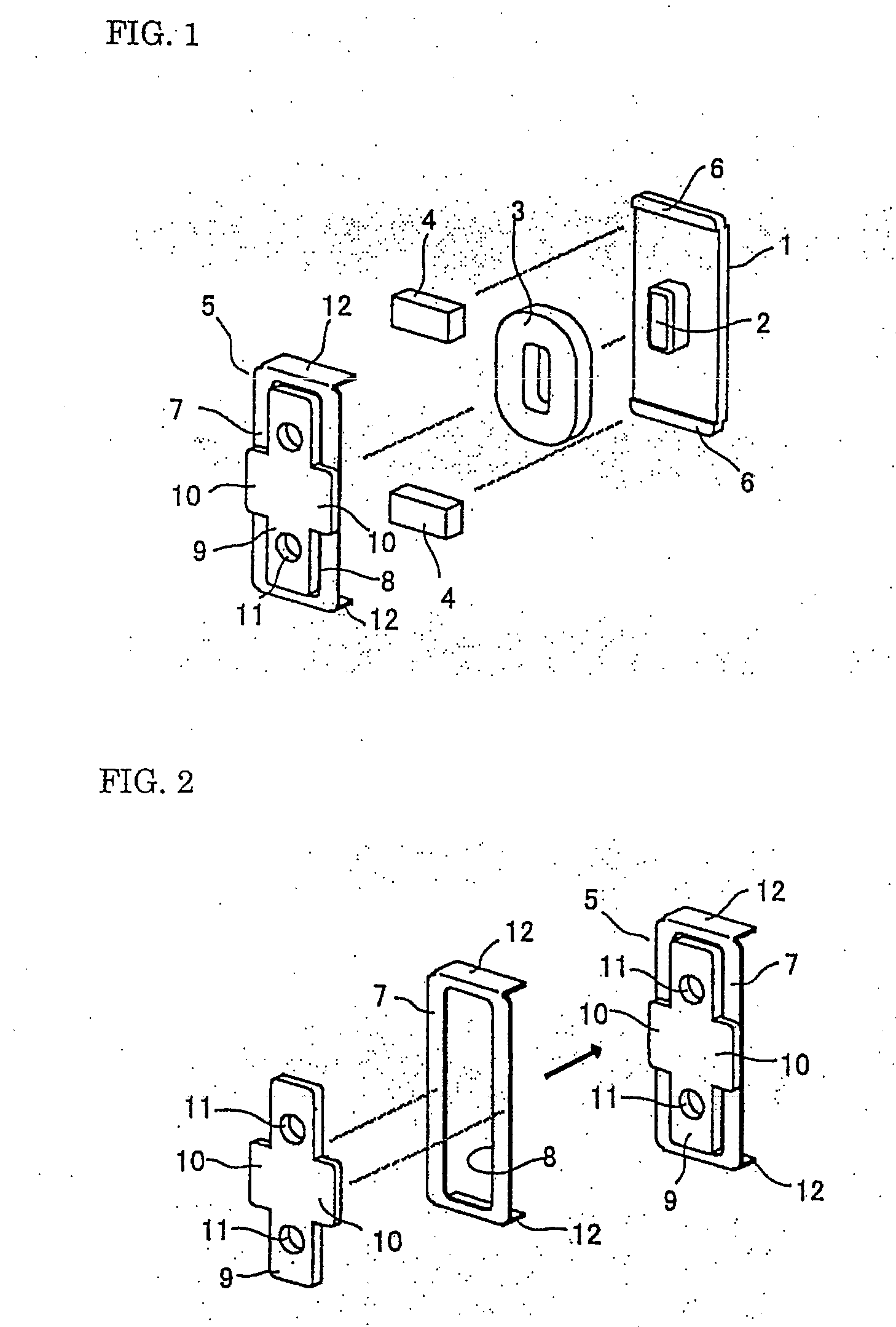
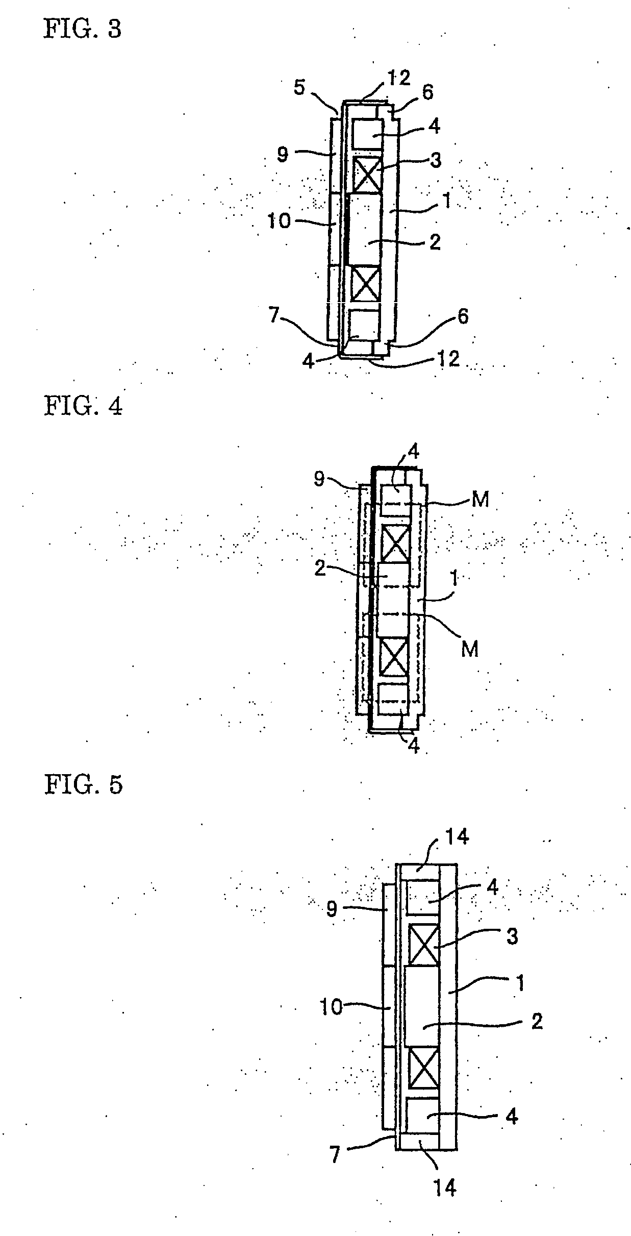
[0020] The bone conduction speaker of the present invention is constructed of: a yoke 1, which is provided with a center magnetic pole 2 assuming a longitudinally elongated shape such as a rectangle, an oval, an ellipse, or the like, wherein the yoke 1 assumes substantially the same longitudinally elongated shape as that of the center magnetic pole 2; a voice coil 3 wound around the center magnetic pole 2 to ...


PUM


Abstract

The object is to provide a bone conduction device and its tympanum, wherein the bone conduction device can be efficiently mounted without generating a dead space in a case having a limited installation space such as a cellular phone's case having a large display screen. A magnetic sound conveter device has an outer magnetic structure wherein a voice coil (3) is mounted on a center magnetic pole (2) of a yoke (1) and a magnet (4) is arranged on the outer side of the voice coil (3). The yoke (1) and the center magnetic pole (2) thereof are vertically long, the magnet (4) is arranged on the short side edge parts on the both sides of the yoke, and a tympanum fixing part (6) is arranged on the outer side of each magnet (4) on a magnet arrangement axis.

Description

TECHNICAL FIELD [0001] The present invention relates to a bone conduction device and a tympanum thereof, and more particularly to a bone conduction device and a tympanum thereof, wherein the bone conduction device comprises: a speaker of a type, which enables a user to catch a voice sound by means of a tympanum having been abutted on a head portion of the user so as to transmit the tympanum's vibrations to the user's bone tissue; and, a bone conduction microphone for picking up a bone conduction sound. BACKGROUND ART [0002] As a conventional bone conduction device, one shown in FIG. 8 has been known in the art. A bone conduction speaker of such a conventional bone conduction device has a construction in which: provided is a yoke 51 provided with a center magnetic pole 52, on which pole 52 a voice coil 56 is wound and mounted thereon; the yoke extends in four directions to form four extension parts, disposed on opposite two ones 53, 53 of which parts are magnets 55, 55, wherein the r...

Claims


Application Information

Patent Timeline
IPC IPC(8): H04R25/00H04R1/00H04R1/10H04R9/02H04R11/06
CPCH04R2460/13H04R11/06H04R1/02H04R7/04H04R25/00H04R9/02
Inventor FUKUDA, MIKIO
Owner TEMCO JAPAN
Learn More