
Multiple-pulses-in-air laser scanning system with ambiguity resolution based on range probing and 3D point analysis

Active Publication Date: 2020-04-16
LEICA GEOSYSTEMS AG
View PDF0 Cites 0 Cited by
  • Summary
  • Abstract
  • Description
  • Claims
  • Application Information

AI Technical Summary

Benefits of technology

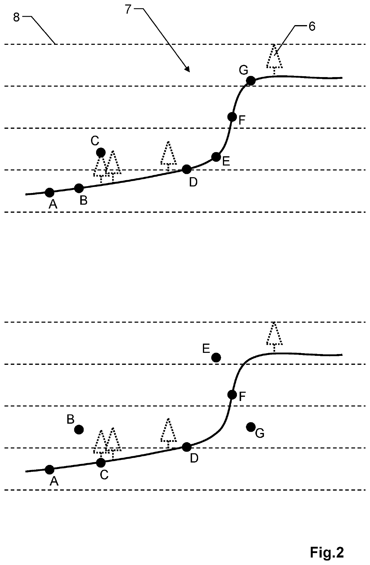
The invention provides an MPiA laser scanning system that is more efficient and robust for measuring distances to targets. The system uses a range probing method where the laser scanner sends pulses at a high frequency, allowing for unambiguous measurement of the distance to the target during flight. The system also uses a spiral scan pattern to minimize shadow effects and reduces errors during analysis. Additionally, intermittent probe values are used to improve accuracy and the system is more robust against noise or sharp changes in the target surface.

Problems solved by technology

However, besides hardware constraints, an increase of the pulse repetition frequency gives rise to the so-called multiple-pulses-in-air (MPiA) problem, also called multiple-time-around (MTA) problem.
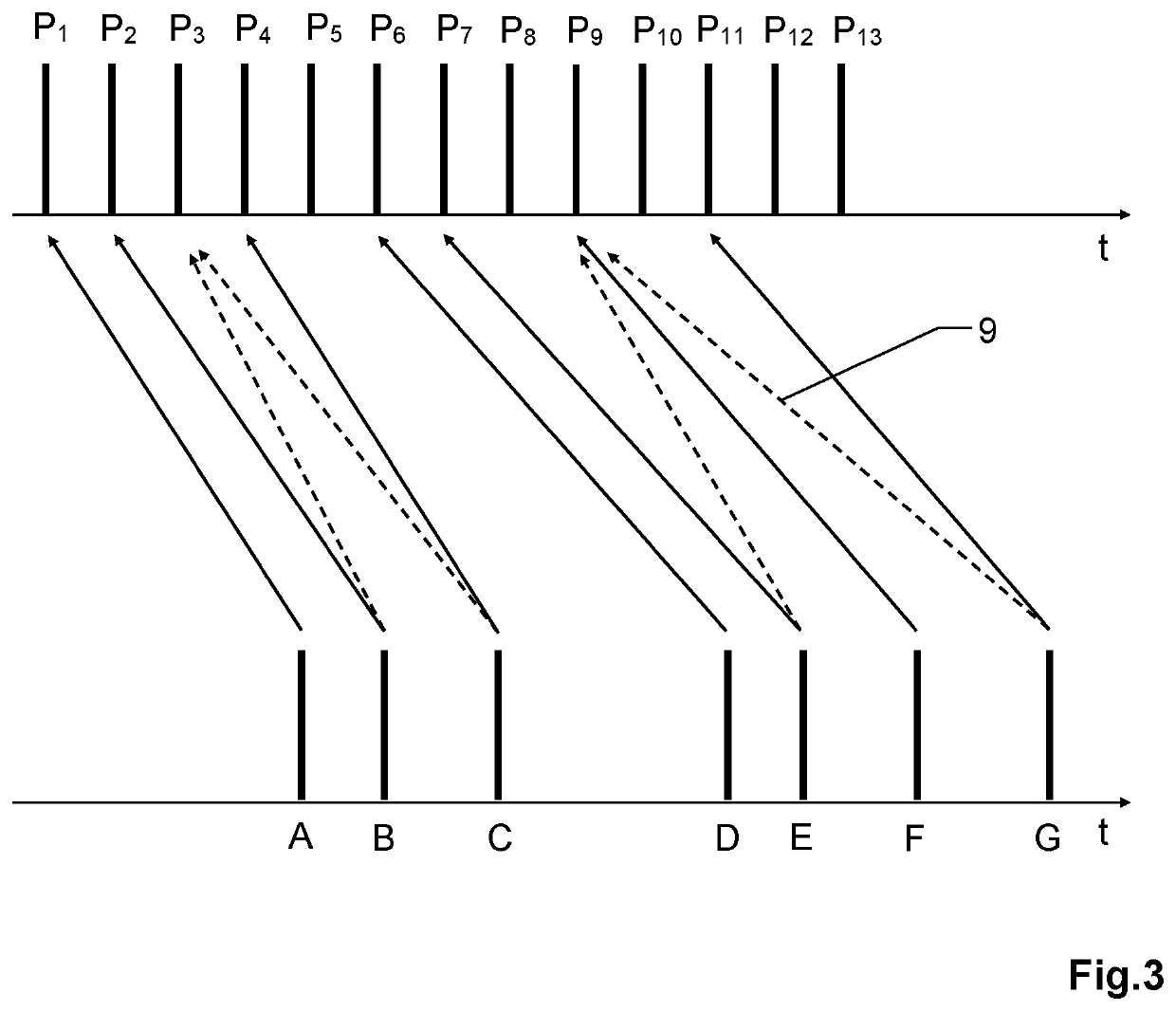
The MPiA problem occurs when the pulse repetition frequency is so high that the time between send pulses is shorter than the time required for an echo to return to the sensor.
This approach has the drawback that the computational complexity rises with the number of MPiA zones that must be accommodated.
Another drawback arises due to the length of the code itself and the fact that all returns from the same sequence will be assigned to the same MPiA zone.
Therefore, such a sequence-based approach will particularly lead to MPiA disambiguation errors in areas of rapidly changing elevation.

Method used


Image

  • Multiple-pulses-in-air laser scanning system with ambiguity resolution based on range probing and 3D point analysis
  • Multiple-pulses-in-air laser scanning system with ambiguity resolution based on range probing and 3D point analysis
  • Multiple-pulses-in-air laser scanning system with ambiguity resolution based on range probing and 3D point analysis

Examples


Embodiment Construction

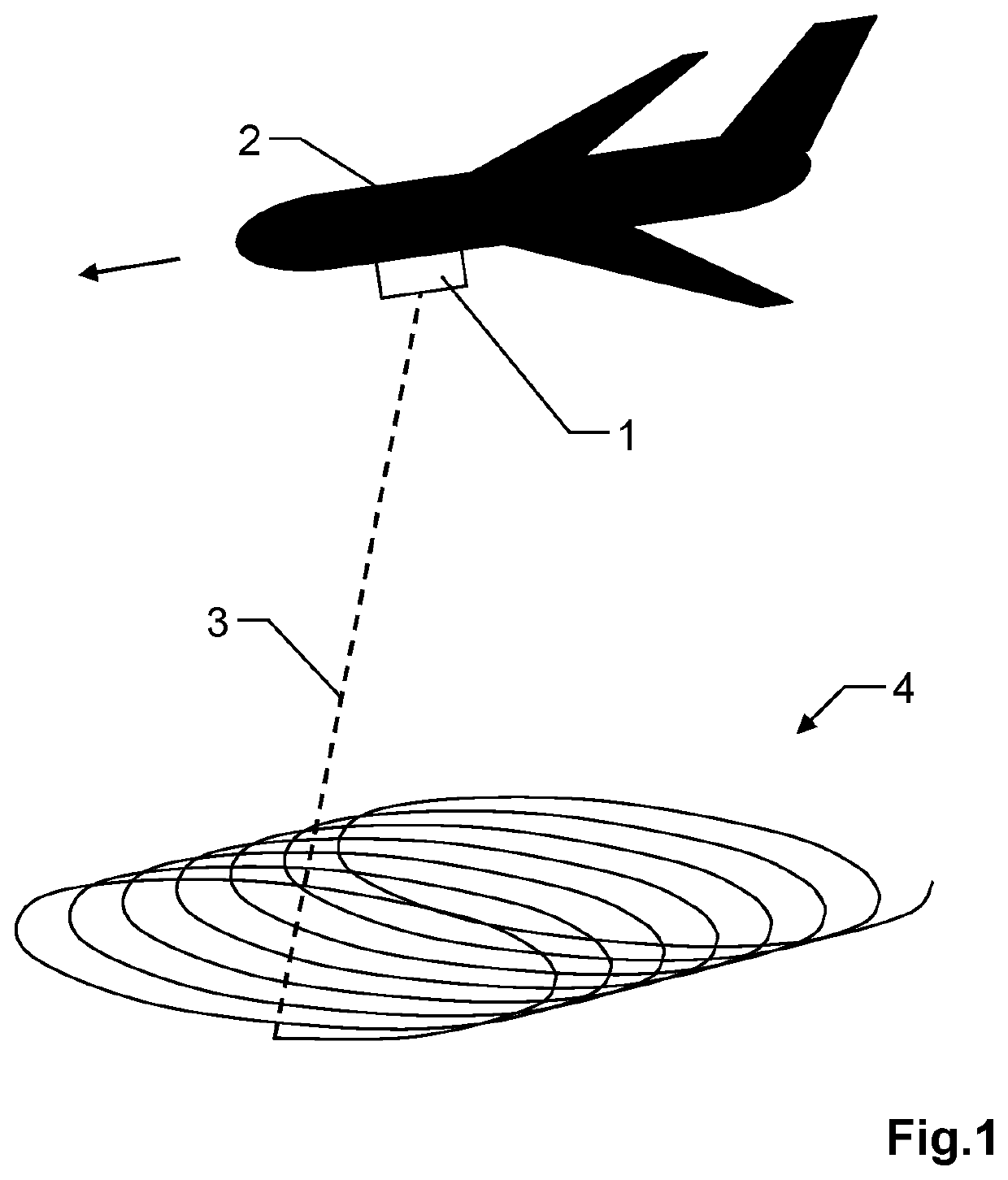
[0057]FIG. 1 shows an exemplary embodiment of the inventive MPiA laser scanner 1 in the field of airborne surveying, wherein the laser scanner 1 is installed in an airborne carrier, e.g. an airplane 2 or satellite. By way of example, the laser scanner 1 is configured for scanning with a circular scan pattern, e.g. using a rotating tilted deflection mirror, wherein an actual scanner pointing direction 3 is indicated. Due to the circular scanning motion by the laser scanner 1 and the forward flight movement of the carrier 2, the surface area is drawing a spiral scan pattern 4 on the ground. Thanks to the spiral scan pattern 4 many surface points will be scanned from two viewing angles, thus minimizing shadow effects.

[0058]Usually several additional or complementary data sources and measuring devices are used for improving or calibrating the LiDAR measurement, particularly additional means for determining the position and orientation of the airborne carrier 2, e.g. comprising an altime...


PUM


Abstract

A multiple-pulses-in-air (MPiA) laser scanning system, wherein the MPiA problem is addressed in that an MPiA assignment of return pulses to send pulses of a laser scanner is based on range tracking and range probing at intermittent points in time. Each range probing comprises a time-of-flight arrangement which is constructed to be free of the MPiA problem. The invention further relates to an MPiA laser scanning system, wherein an MPiA ambiguity within a time series of return pulses, is converted into 3D point cloud space, which provides additional information from the spatial neighborhood of the points in question to enable MPiA disambiguation.

Description

FIELD OF INVENTION[0001]The present invention relates to a multiple-pulses-in-air (MPiA) laser scanning system for measuring the time-of-flight of laser pulses of a laser scanner. Furthermore, the invention relates to a computer program product for measuring the time-of-flight of laser pulses of a laser scanner.BACKGROUND[0002]Pulse time-of-flight measuring systems are standard solutions nowadays in many different fields of application. The principle used herein substantially consists of emitting pulsed electromagnetic radiation onto a target to be surveyed and subsequently receiving the radiation that is returned by the target, wherein the distance to the target is determined on the basis of the time of flight of the pulses, i.e. the time difference between the transmission of a laser pulse (send pulse) and the reception of its echo (return) coming back from a surface. Using the speed of light, the range to the surface may be then be calculated using this measurement.[0003]By way o...

Claims


Application Information

Patent Timeline
IPC IPC(8): G01S7/486G01C15/00G01S7/48G01S17/89
CPCG01C15/002G01S7/4808G01S17/89G01S7/4861G01S17/08G01S17/88G01S7/4865G01S7/4817G01S17/42G01S7/487G01S17/10
Inventor YANG, QUANPAN, ZHIGANGSANDERS, III, JAMES CHESTER
Owner LEICA GEOSYSTEMS AG
Learn More