
Fundus Observation Device

a technology of observation device and fundus, which is applied in the field offundus observation device, can solve the problems of difficult to capture the detailed state of the fundus surface or the entire retina, difficult to capture the 2-dimensional surface image of the fundus of the eye to be examined by a fundus camera, and difficult to capture the 3-dimensional image of the optical image measuring device, etc., to achieve clear and high-efficiency, control the effect of interference efficiency and high interference efficiency

Active Publication Date: 2007-07-12
KK TOPCON
View PDF11 Cites 32 Cited by
  • Summary
  • Abstract
  • Description
  • Claims
  • Application Information

AI Technical Summary

Benefits of technology

[0050] The fundus observation device related to the first embodiment comprises a first image forming means for forming 2-dimensional images of the surface of the fundus oculi and a second image forming means for forming tomographic images of the fundus oculi. The imaging optical system of the first image forming means forms the optical path for imaging. The second image forming means generates the interference light by overlapping the signal light passing through the fundus oculi to the reference light, and forms tomographic images of the fundus oculi based on this interference light.
[0051] Optical combination and separation means operates to combine the optical path of the signal light toward the fundus oculi and the optical path for imaging. The signal light irradiates onto the fundus oculi through this optical path for imaging. Also, optical combination and separation means operates to separate the signal light toward the fundus oculi from the optical path for imaging. The separated signal light generates the interference light by overlapping the reference light.
[0052] Such optical combination and separation means permits to capture both 2-dimensional images of the surface of the fundus oculi and tomographic images of the fundus oculi. In particular, when the illumination light from the first image forming means irradiates and the illumination from the signal light by the second image forming means irradiate simultaneously, each light through the fundus oculi is separated by the optical path combination and separation means, and each light is detected so that the image is formed. Therefore, the fundus observation device related to the present invention allows both 2-dimensional images of the surface of the fundus oculi and tomographic images of the fundus oculi to be captured simultaneously.
[0053] Additionally, by the fundus observation device according to the second embodiment, because it has dispersion assignment means for allowing dispersion of the reference light, it can reimburse at least one part of the dispersion assignment to the signal light when the optical path for imaging passes through. As a result, it can control the decrease in interference efficiency for both the signal light and the reference light.
[0054] In particular, the fundus observation device according to the third embodiment, during the time from splitting by the interference light generating means through the fundus oculi to overlapping with the reference light, can comprise the dispersion assignment means for allowing dispersion assignment to the signal light and the dispersion which substantially equals the reference light, so it is almost equal to each dispersion assignment for overlapping both the signal light and the reference light on each other. As a result, it can interfere with the signal light and the reference light with high interference efficiency, allowing it to capture clear and highly accurate tomographic images (OCT images).
[0055] Moreover, by the fundus observation device according to the fourth embodiment, it is possible for the total value of the dispersion of several optical elements through which the signal light passes during the time from splitting by interference light generating means to overlapping with the reference light through the fundus oculi and the total value of the dispersion of several optical elements through the reference light to be substantially equal, and therefore, it is almost equal to the dispersion allowing both the signal light and the reference light to overlap each other, allowing it to interfere with both the signal light and the reference light with high interference efficiency.

Problems solved by technology

However, by just observing an image .of the fundus surface obtained from a fundus camera, it is difficult to capture the state of the deep layer tissues in detail, while, with tomographic images of the fundus oculi obtained from an optical image measuring device, it was difficult to capture the detailed state of the fundus surface or the entire retina.
However, with conventional fundus observation devices, it was difficult to capture both a 2-dimensional surface image of the fundus of an eye to be examined by a fundus camera, a tomographic image of the fundus, and a 3-dimensional image by an optical image measuring device.
In particular, it was difficult to capture both fundus images at the same time.
Thus, due to the effect of the dispersion of these optical elements, the interference efficiency of the signal light and the reference light decreases such that sufficient intensity interference light may not be generated.
Therefore, when the image is formed based on the deficient intensity interference light, the OCT image is of low contrast and is unclear, as with a conventional optical image measuring device.
But for both fundus images by a fundus camera and fundus images by an optical image measuring device of an adequate fundus observing device, there is a large difference between the number of optical elements passing through the signal light and the number of optical elements passing through the reference light such that there is a difference between the effect of dispersion to the signal light and the effect of dispersion to the reference light, and correction by the image processing may be insufficient.

Method used


Image

  • Fundus Observation Device
  • Fundus Observation Device
  • Fundus Observation Device

Examples


embodiment 1

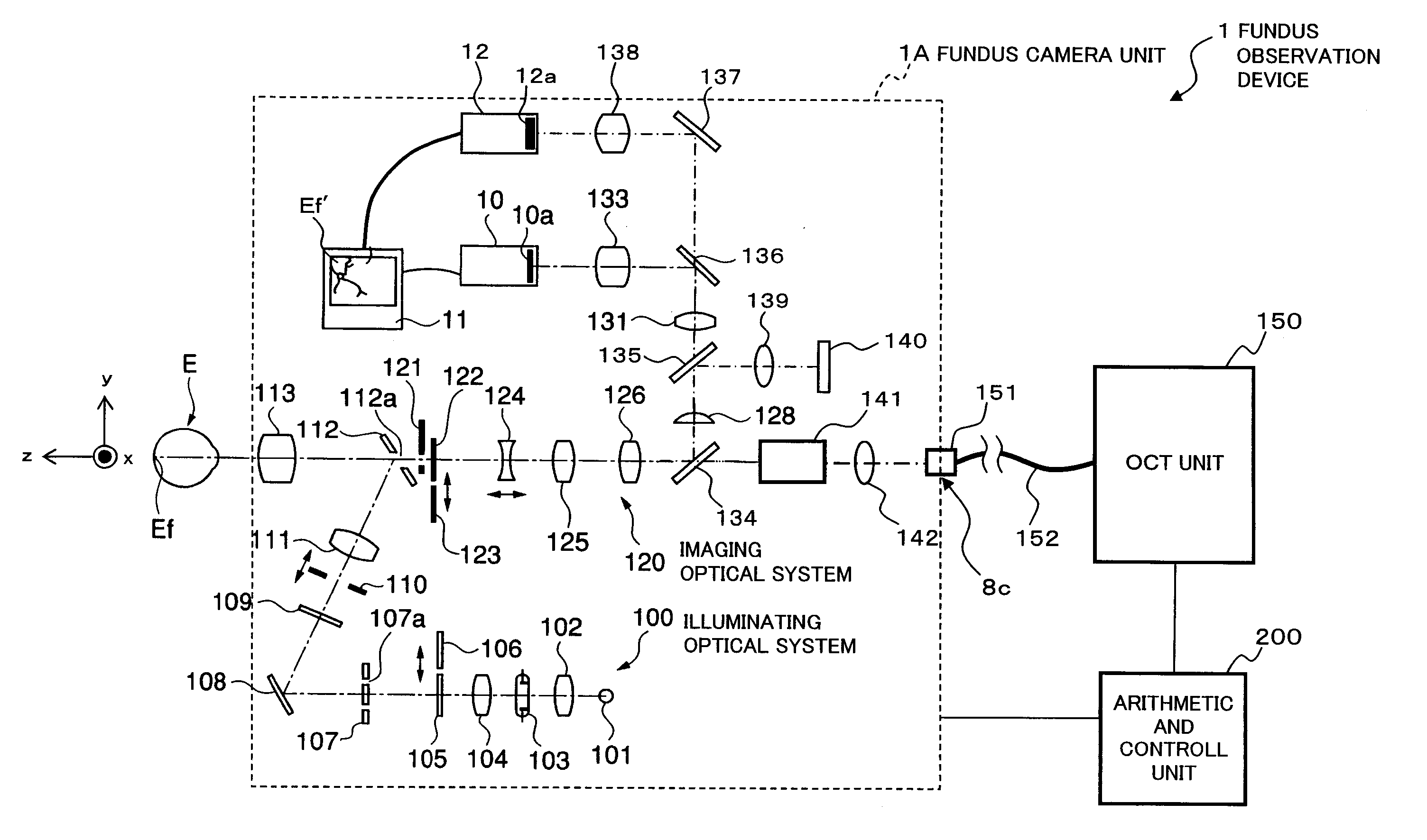
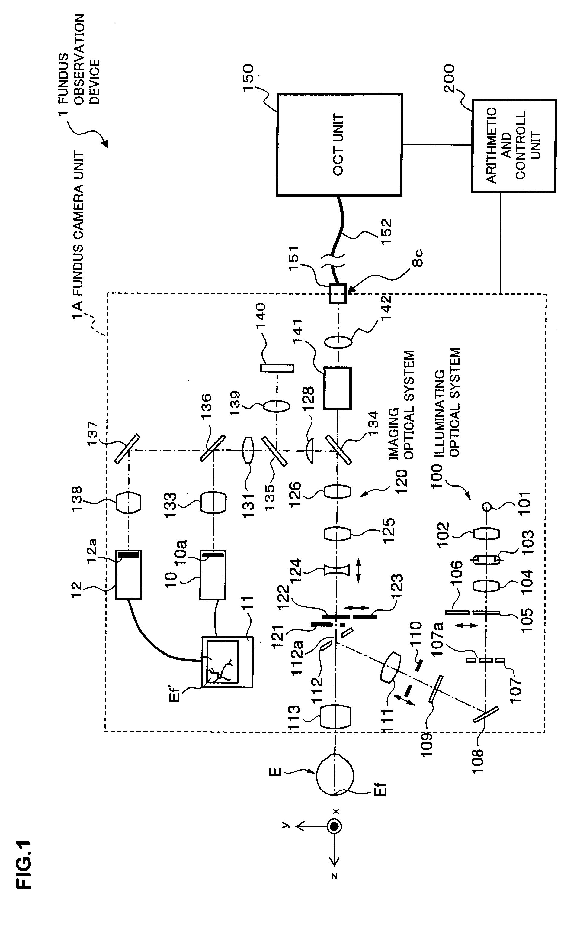
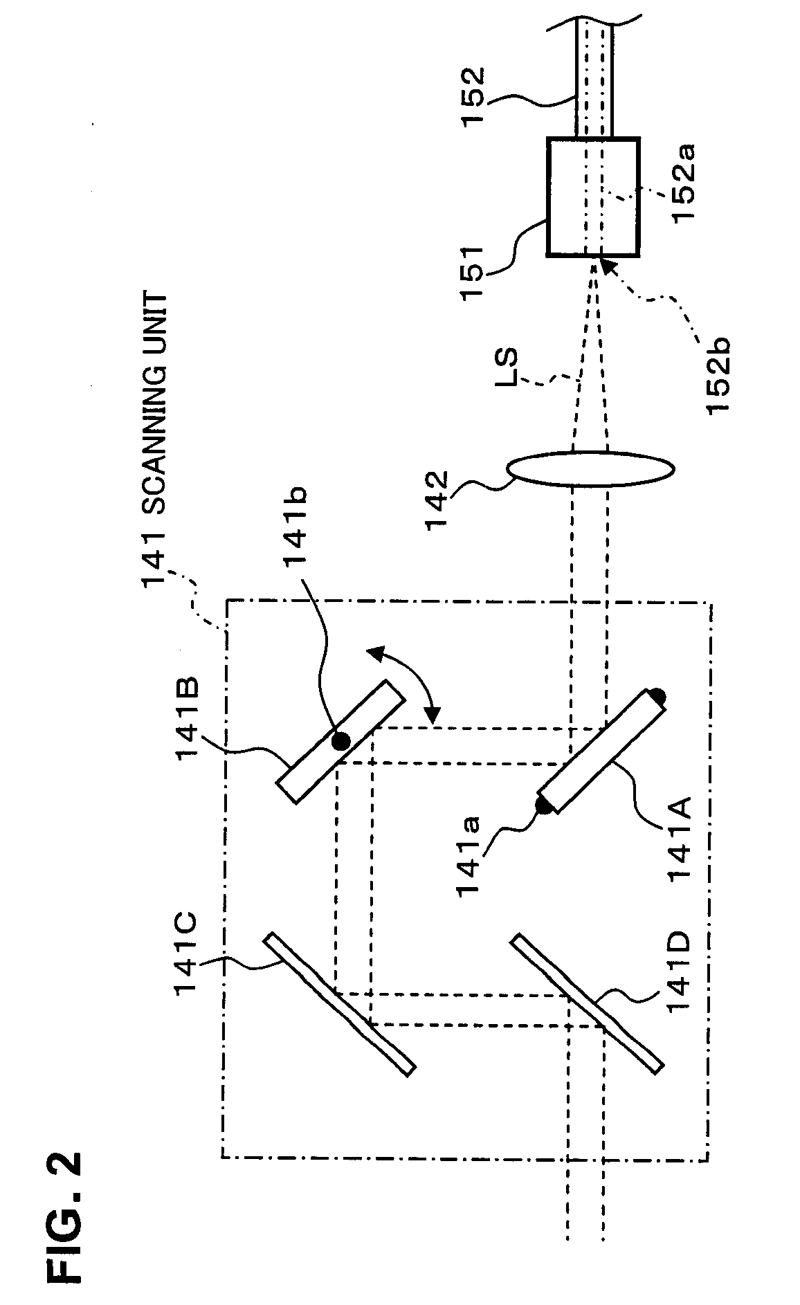
[0069] First, by referring to FIGS. 1 through 5, the constitution of Embodiment 1 of the fundus observation device related to the present invention is described. FIG. 1 shows the entire constitution of the fundus observation device 1 related to the present invention. FIG. 2 shows a constitution of a scanning unit 141 in a fundus camera unit 1A. FIG. 3 shows a constitution of an OCT unit 150. FIG. 4 shows a hardware configuration of an arithmetic and control unit 200. FIG. 5 shows a configuration of a control system of the fundus observation unit 1.

The Entire Constitution

[0070] As shown in FIG. 1, the fundus observation device 1 is comprised of a fundus camera unit 1A that functions as a fundus camera, an OCT unit 150 accommodating the optical system of an optical image measuring device (OCT device), and an arithmetic and control unit 200 that executes various control processes, etc.

[0071] This fundus camera unit 1A is a component of one embodiment of the “first image forming mea...

modified example

[0156] The constitution described above is merely one example to preferably implement the fundus observation device related to the present invention. Therefore, optional modifications may be implemented appropriately within the scope of the present invention.

[0157] For example, in the above embodiment, as the low coherence light LO, near-infrared light with a wavelength of about 800 nm to 900 nm is used, but light of longer wavelengths can be used to measure images in the deeper region of the fundus oculi Ef. For example, near-infrared light of a wavelength within about 900 nm to 1000 nm is used, and also near-infrared light of a wavelength within about 1000 nm to 1100 nm can be used.

[0158] Moreover, when low coherence light LO of a wavelength within about 900 nm to 1000 nm is used, the near-infrared light of a wavelength within about 700 nm to 900 nm can be used as the illumination light for the fundus camera unit 1A. Moreover, when the low coherence light LO of a wavelength with...

embodiment 2

[0161] The fundus observation device related to Embodiment 2 is described. The fundus observation device of the embodiment has the same constitution of the fundus observation device 1 of the first embodiment (see FIG. 1 to FIG. 4). Moreover, the scanning features of signal light by the fundus observation device of the embodiment and the forming features of tomographic images are the same as FIG. 6 and FIG. 7. The fundus observation device of the present embodiment is described below with regard to the differences from Embodiment 1.

[0162]FIG. 8 shows one example of the constitution of a control system of the fundus observation device of this embodiment. The fundus observation device 20 shown in the same figure is provided with a fundus camera unit 1A, an OCT unit 150 and an arithmetic and control unit 200.

[0163] Herein, the constitution of the optical path of the reference light LR is described. First, an optical fiber 163 guiding the reference light LR has a constitution such that...


PUM


Abstract

A fundus observation device which can simultaneously capture both surface images and tomographic images of the fundus oculi is provided. The fundus observation device 1 has a fundus camera unit 1A, an OCT unit 150, and an arithmetic and control unit 200. The fundus camera unit 1A has an illuminating optical system 100 and an imaging optical system 120. The arithmetic and control unit 200 forms the surface image of fundus oculi Ef based on signals from fundus camera unit 1A. The OCT unit 150 divides low coherence light LO into the signal light LS and the reference light LR, and detects the interference light LC that can be obtained from the signal light LS passing through fundus oculi Ef and the reference light LR passing through reference mirror 174. The arithmetic and control unit 200 forms tomographic images of fundus oculi Ef based on these detecting results. A Dichroic mirror 134 combines the optical path of the signal light LS toward fundus oculi Ef into the optical path for imaging of the imaging optical system 120, and separates the optical path of the signal light LS towards fundus oculi Ef from the optical path for imaging.

Description

BACKGROUND OF THE INVENTION [0001] 1. Field of the Invention [0002] The present invention relates to a fundus observation device, for observing the state of the fundus oculi of an eye to be examined. [0003] 2. Description of the Related Art [0004] As a fundus observation device, conventionally a fundus camera has been widely used. FIG. 9 shows one example of the appearance of a conventional fundus camera in general, and FIG. 10 shows one example of an optical system composition to be internally accommodated therein (e.g. JP Patent laid-open No. 2004-350849). Furthermore, “observation” is intended to include at least a case in which produced fundus images are observed (fundus observations with the naked eye may be included). [0005] First, referring to FIG. 9, an explanation is made regarding the appearance of a conventional fundus camera 1000. This fundus camera is provided with a platform 3 mounted on a base 2 slidably in the front and rear, right and left (horizontal direction) dir...

Claims


Application Information

Patent Timeline
IPC IPC(8): A61B3/14
CPCA61B3/12A61B3/102
Inventor FUKUMA, YASUFUMIOTSUKA, HIROYUKIYUMIKAKE, KAZUHIKO
Owner KK TOPCON
Learn More