
Systems and methods for peritoneal dialysis

a technology of peritoneal dialysis and system, applied in the field of systems, can solve the problems of inability to balance water, minerals and excretion of daily metabolic load, inability to eliminate toxic end products of nitrogen metabolism (e.g., urea, creatinine, uric acid, etc.) and achieve the effect of optimizing the use of dialysate, improving system and method, and minimizing treatment tim

Inactive Publication Date: 2007-07-12
BAXTER INT INC +1
View PDF5 Cites 28 Cited by
  • Summary
  • Abstract
  • Description
  • Claims
  • Application Information

AI Technical Summary

Benefits of technology

The present invention relates to systems and methods for providing peritoneal dialysis therapy. The invention includes a closed fluid path that allows for the reuse of dialysate during treatment, resulting in more efficient use of the dialysate and reduced treatment times. The dialysate is cleaned and returned to the patient's peritoneal cavity for reuse, with a cleaning device that removes solutes and excess water from the dialysate. The invention also includes the use of a single fluid path, which minimizes the amount of dialysate needed for effective treatment. The therapy fluid can be adjusted to control the solute level, and additional solutions can be added to further enhance solute removal. The invention provides improved systems and methods for peritoneal dialysis therapy.

Problems solved by technology

Due to disease, insult or other causes, a person's renal system can fail.
The balance of water, minerals and the excretion of daily metabolic load is no longer possible in renal failure.
During renal failure, toxic end products of nitrogen metabolism (e.g., urea, creatinine, uric acid, and others) can accumulate in blood and tissues.
Consequently, contamination of such a dialysis system can be problematic.
Thus, the dialysate fluid exiting the REDY™ cartridge is not suitable for peritoneal dialysis.
Manual peritoneal dialysis performed by the patient requires a significant amount of time and effort from the patient.
In this regard, the volume of dialysate necessary to carry out treatment for a continuous flow single use or pass system can be large in size rendering their daily use cost prohibitive.
However, the removal of ammonia can be problematic and thus may not provide a failsafe measure.
This can add to the complexity of the therapy and thus increase the cost associated with same.

Method used


Image

  • Systems and methods for peritoneal dialysis
  • Systems and methods for peritoneal dialysis
  • Systems and methods for peritoneal dialysis

Examples


Embodiment Construction

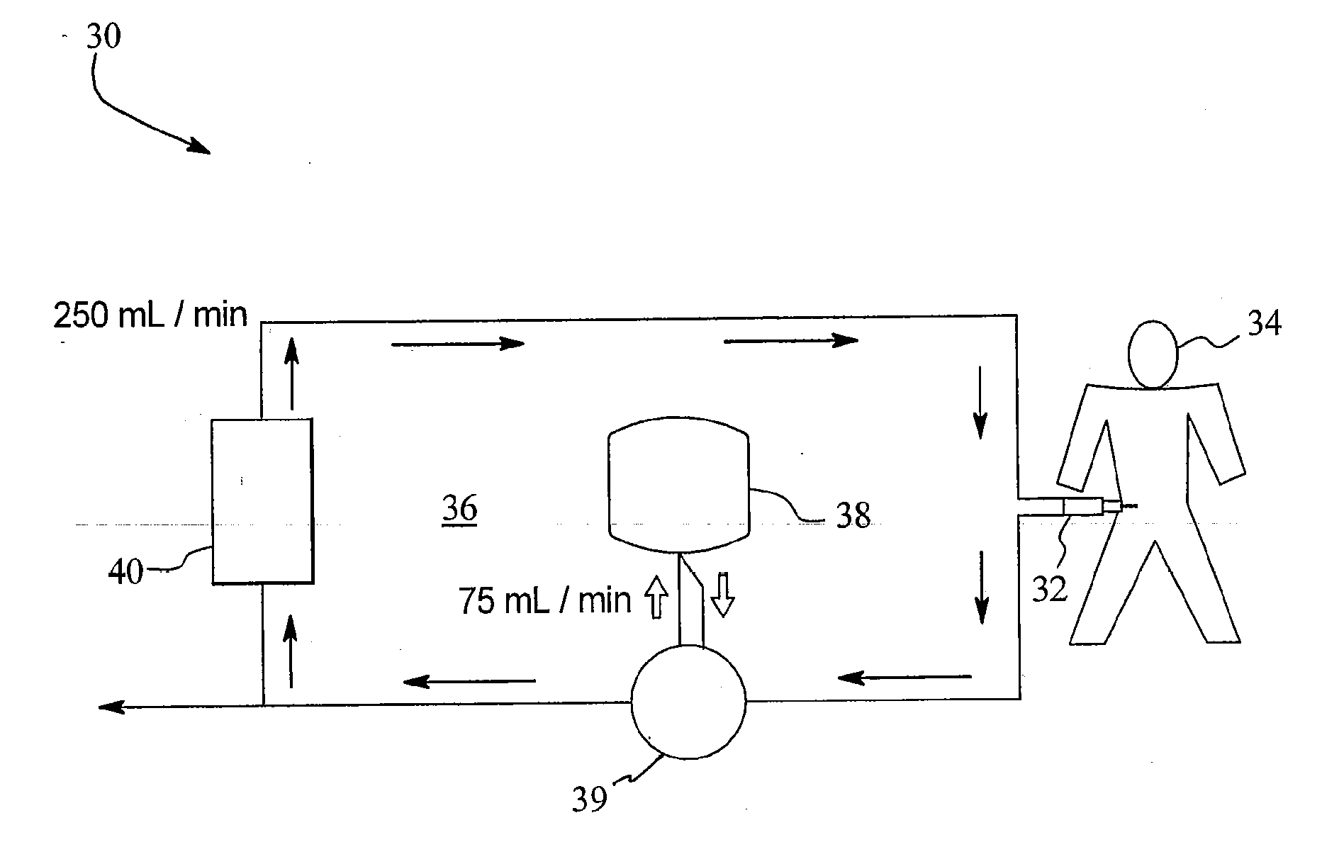
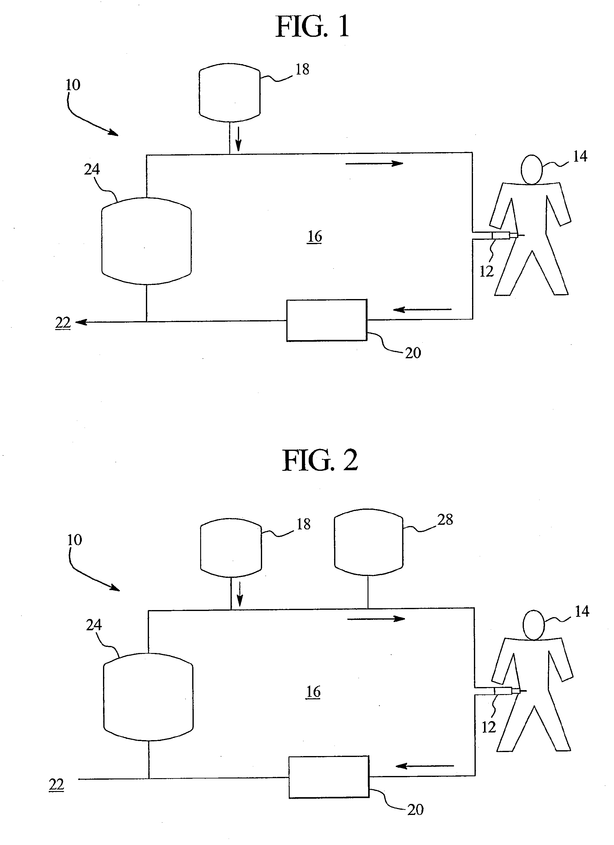
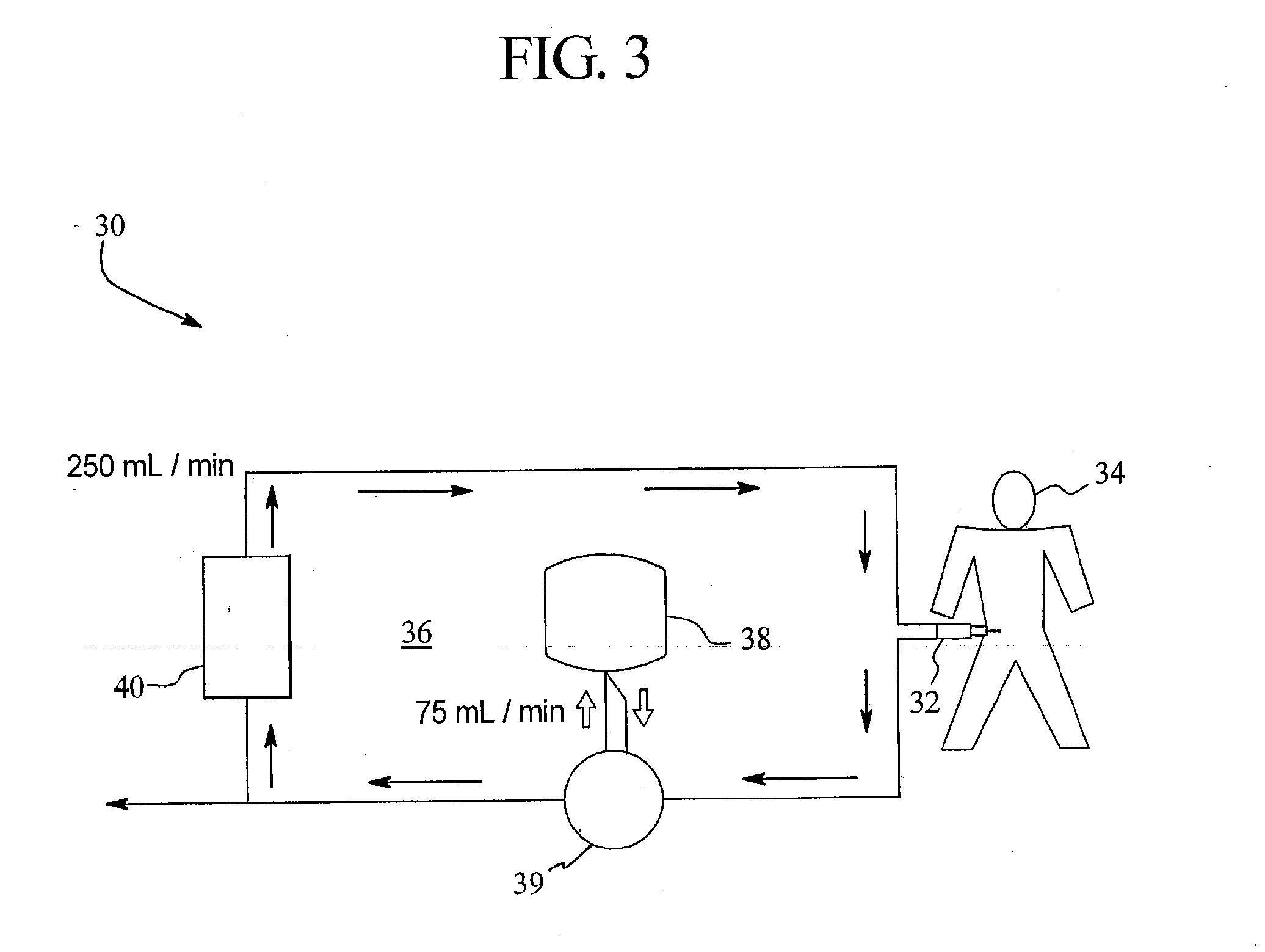
[0035] In general, the present invention employs a single closed fluid path along which a minimal volume of therapy fluid can be circulated such that the therapy fluid can pass into, through and out of a peritoneal cavity of a patient connected to the closed fluid path to effectively remove solutes, excess water and the like from the patient during treatment. In an embodiment, the available volume of therapy fluid can include about 6 liters or less of an initial source of dialysate. It is believed that the available volume of therapy fluid can be circulated along the closed fluid path to remove solutes from the patient at or exceeding clinically acceptable solute removal standards, such as the National Kidney Foundation's DOQI levels. In an embodiment, acceptable solute removal or clearance levels can be achieved over a period of 8 hours or less, preferably 7 hours or less, during treatment.

[0036] For example, it is believed that a therapeutic level of clearances can be achieved fo...


PUM

PropertyMeasurementUnit
sizeaaaaaaaaaa
volumeaaaaaaaaaa
volumeaaaaaaaaaa

Abstract

Systems and methods relating to dialysis therapy, particularly continuous flow dialysis therapy, are provided. The present invention includes a single closed fluid path along which a minimal amount of therapy fluid including dialysate is fed into, continuously circulated and cleaned such that a therapeutic effective amount of solutes, excess water and the like can be removed from the patient connected to the closed fluid loop during treatment.

Description

PRIORITY CLAIM [0001] This application is a continuation of U.S. patent application Ser. No. 10 / 623,317, filed Jul. 17, 2003, and also claims the benefit of U.S. Provisional Pat. Appl. No. 60 / 397,045, filed Jul. 19, 2002, both entitled “Systems And Methods For Peritoneal Dialysis”; the entire contents of both applications are hereby incorporated by reference and relied upon.BACKGROUND OF THE INVENTION [0002] The present invention generally relates to systems and methods for providing peritoneal dialysis. More specifically, the present invention relates to systems and methods for providing continuous flow peritoneal dialysis. [0003] Due to disease, insult or other causes, a person's renal system can fail. In renal failure of any cause, there are several physiological derangements. The balance of water, minerals and the excretion of daily metabolic load is no longer possible in renal failure. During renal failure, toxic end products of nitrogen metabolism (e.g., urea, creatinine, uric...

Claims


Application Information

Patent Timeline
Patent Type & Authority Applications(United States)
IPC IPC(8): B01D61/00B01D11/00C02F1/44A61M1/14A61M1/16A61M1/28
CPCA61M1/1696A61M2202/0021A61M1/284A61M1/28A61M1/166
Inventor MICHELI, BRIAN R.
Owner BAXTER INT INC
Learn More