
Slider window assembly

a technology for sliding windows and assemblies, applied in the direction of wing accessories, transportation and packaging, wing arrangements, etc., can solve the problems of large assembly volume, large number of components, and low quality of prior slider window assemblies, and achieve the effect of low cost and high quality

Inactive Publication Date: 2007-07-12
DURA GLOBAL TECH
View PDF17 Cites 70 Cited by
  • Summary
  • Abstract
  • Description
  • Claims
  • Application Information

AI Technical Summary

Benefits of technology

[0013] From the foregoing disclosure and the following more detailed description of various preferred embodiments it will be apparent to those skilled in the art that the present invention provides a significant advance in the technology and art of slider window assemblies. Particularly

Problems solved by technology

Prior slider window assemblies are mechanically complex having large numbers of components.
This large number of components requires a relatively large amount of assembly and results in a relatively large cost.
Additionally, current slider window assemblies are relatively heavy.
Prior slider window assemblies also do not seal well resulting in air and water leakage.
Some window assemblies have frame members at the interface between the fixed window and the motor vehicle body that cause leakage while others have bulb seals at the sliding window that cause leakage because it is difficult to balance the high contact force required for a bulb seal and the difficulty to open the sliding window when there is high contact force.
Additionally, rails for the sliding panels tend to collect water which can inhibit proper functioning of the window assembly.
As a result, costly water management systems have been used which direct accumulated water from within the guide rails to locations outside the vehicles.

Method used


Image

  • Slider window assembly
  • Slider window assembly
  • Slider window assembly

Examples


Embodiment Construction

[0036] It will be apparent to those skilled in the art, that is, to those who have knowledge or experience in this area of technology, that many uses and design variations are possible for the improved slider window assemblies disclosed herein. The following detailed discussion of various alternative and preferred embodiments will illustrate the general principles of the invention with reference to a semi-flush slider window assembly for use as a backlight of a pickup or other light duty truck. Other embodiments suitable for other applications will be apparent to those skilled in the art given the benefit of this disclosure.

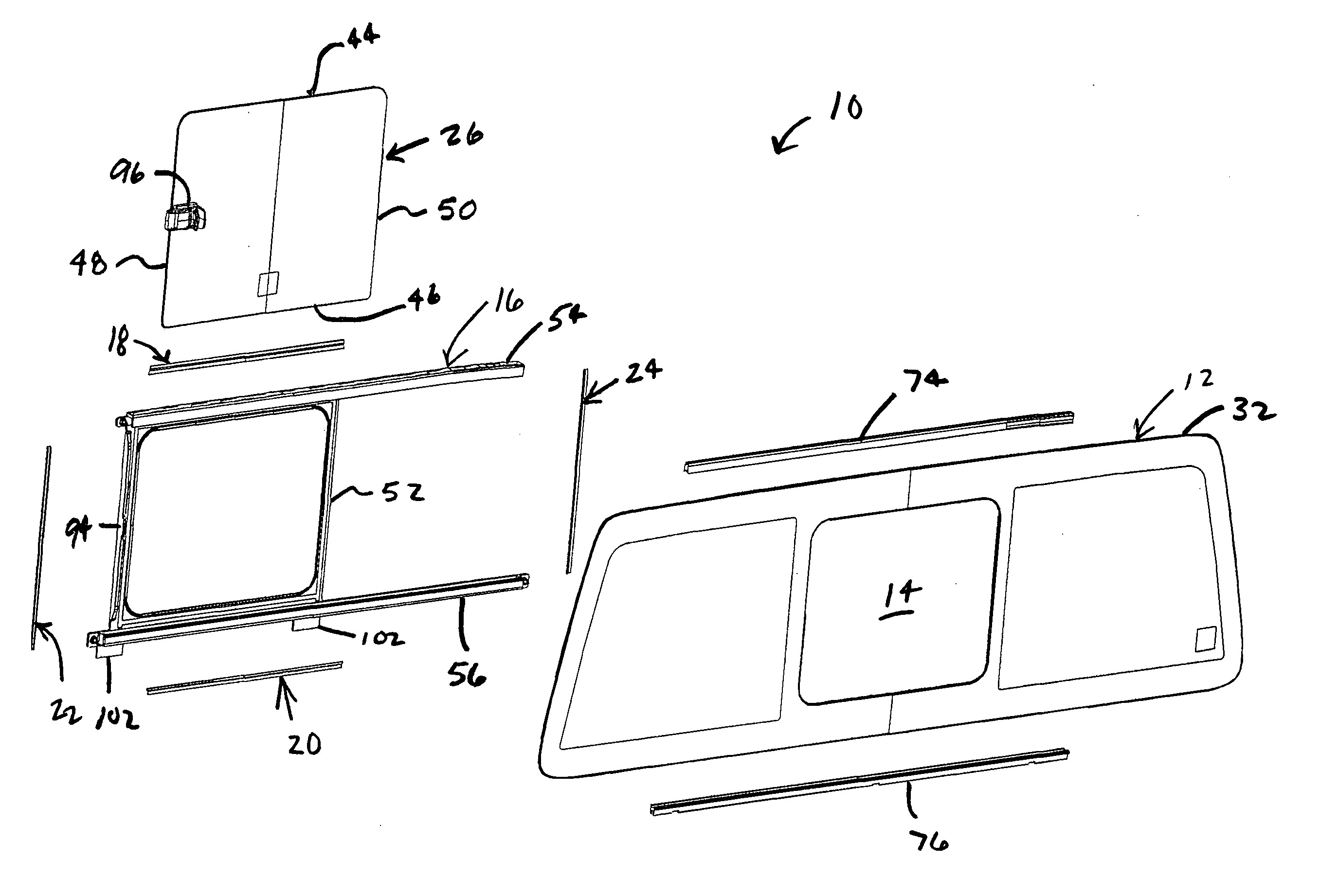
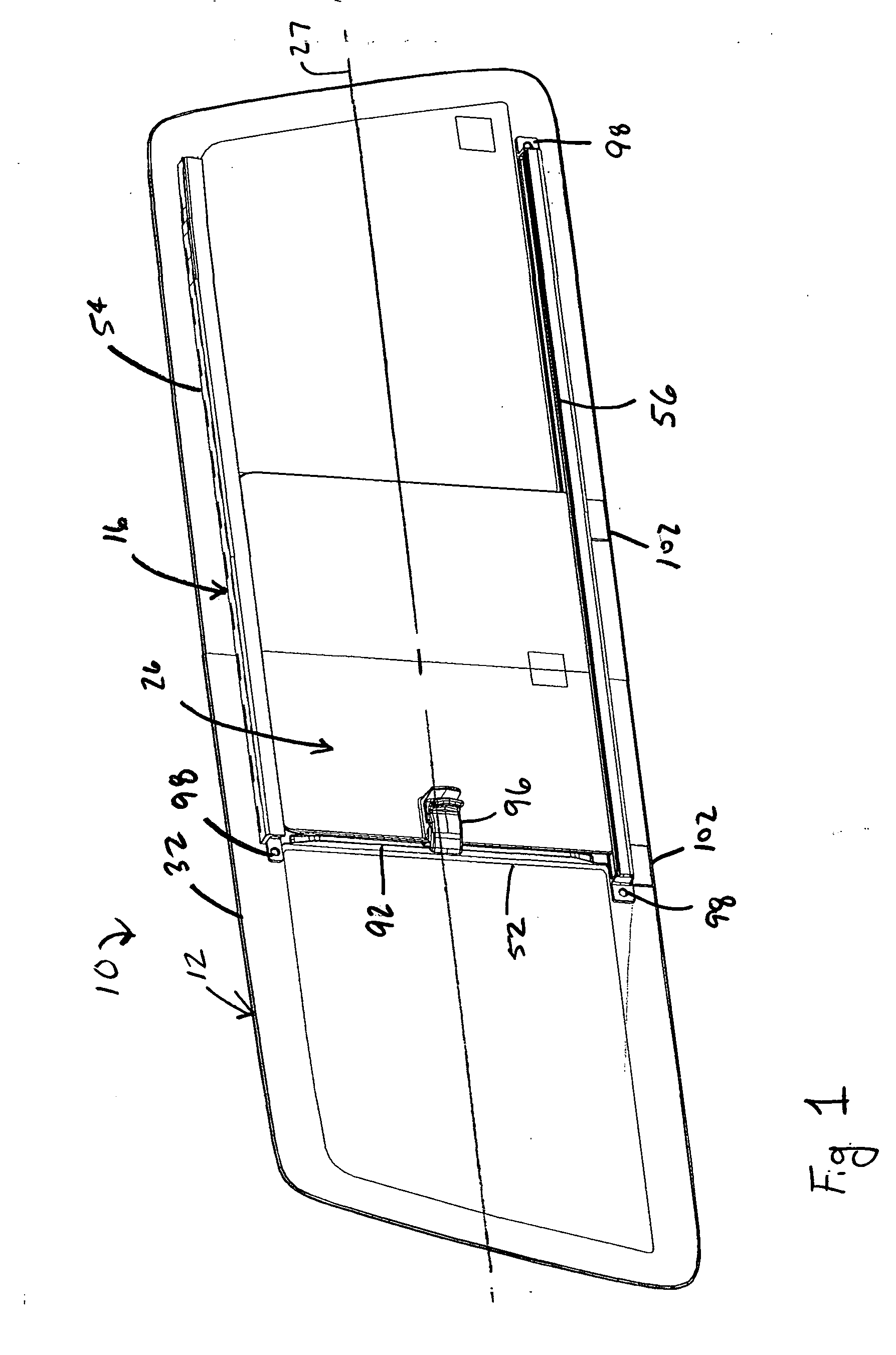
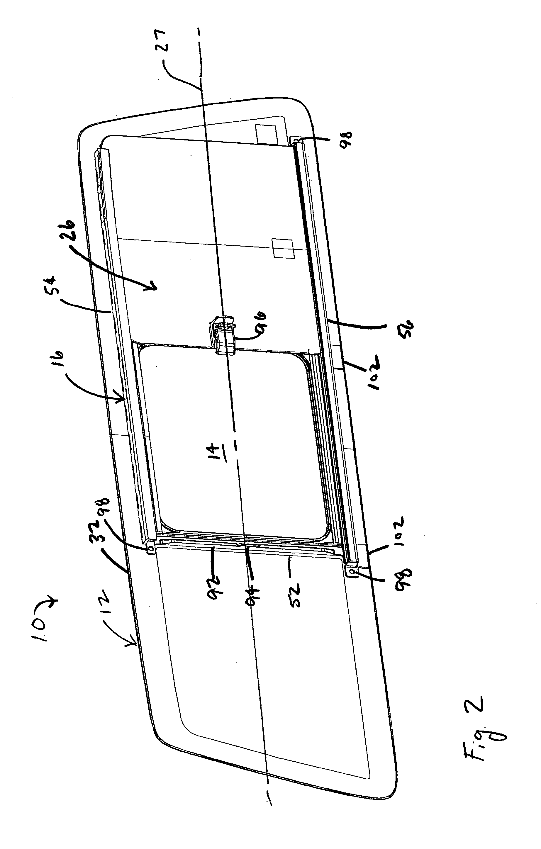
[0037] Referring now to the drawings, FIGS. 1 to 15 show a slider window assembly 10 for a motor vehicle according to the present invention. The illustrated slider window assembly 10 includes a static or fixed panel 12 having an opening 14 formed therein, a unitary slider frame 16 secured to the fixed panel 12 about the opening 14, at least one seal member 18, 2...


PUM


Abstract

A slider window assembly for a motor vehicle includes a fixed panel formed of a single pane encircling an opening formed therein, a slider panel movable along a horizontal axis between closed and open positions, an injection-molded plastic slider frame adhesively bonded to the fixed panel, and at least one seal member forming a seal between the slider frame and the slider panel. The slider frame includes a sealing frame extending entirely about the opening, an upper run located above the opening and receiving the slider panel, and a lower run located below the opening and receiving the slider panel. There is preferably a substantially continuous adhesive bond between the slider frame and the fixed panel that entirely encircles the opening.

Description

CROSS-REFERENCE TO RELATED APPLICATIONS [0001] Not Applicable. STATEMENT REGARDING FEDERALLY SPONSORED RESEARCH [0002] Not Applicable REFERENCE TO MICROFICHE APPENDIX [0003] Not Applicable FIELD OF THE INVENTION [0004] The present invention generally relates to window assemblies for motor vehicles and, more particularly, to widow assemblies for motor vehicles having a window panel movable into a closed and sealed position over an opening in a static window panel. BACKGROUND OF THE INVENTION [0005] Many motor vehicles such as, for example, pickup trucks and vans have window assemblies with large fixed glass panels. To improve circulation within the vehicle, these fixed window panels are sometimes provided with sliding window panels or “sliders” that move between an open position to provide a window opening in the fixed window panel and a closed position to close the window opening. For example, passenger compartments of pickup trucks and other light trucks often have rearward facing ...

Claims


Application Information

Patent Timeline
IPC IPC(8): E05D15/06
CPCB60J1/1853
Inventor HEBERT, BRYAN EMILECICALA, ROBERT JOHNKECK, KENNETH E. II
Owner DURA GLOBAL TECH
Learn More