
Handheld medical device programmer

a medical device and programmer technology, applied in the field of hand-held medical device programmer, can solve the problems of not providing continuous data, difficult to maintain, and difficult to provide continuous data, and achieve the effect of increasing the maximum distan

Inactive Publication Date: 2007-07-05
MEDTRONIC INC
View PDF99 Cites 472 Cited by
  • Summary
  • Abstract
  • Description
  • Claims
  • Application Information

AI Technical Summary

Benefits of technology

[0011] In yet further embodiments, the remote programmer further includes a transmitter coupled to the at least one processor and the input / output port. The at least one processor further includes the ability to program other medical devices, and the transmitter transmits a program to the other medical devices. In particular embodiments, the transmitter transmits through a relay device between the transmitter and a remotely located processing device. In some embodiments, the relay device increases a maximum distance by amplifying the processed sensor data signals from the transmitter to be received by the remotely located processing device. In other embodiments, the relay device enables the remotely located processing device to be located in a different room than the transmitter. While in other embodiments, the relay device includes a telecommunications device, and when the transmitter generates an alarm the telecommunications device transmits the alarm to a remotely located receiving station. Further embodiments of the remote programmer include a data receiver, and the data receiver receives program instructions from other processing devices.

Problems solved by technology

This results in discomfort from the lancet as it contacts nerves in the subcutaneous tissue.
In addition, these blood glucose meters are only designed to provide data at discrete points, and even with multiple tests a day, do not provide continuous data to show the variations in the characteristic between testing times.
However, the monitors and electrochemical sensors often require calibration using readings obtained from blood glucose meters to augment and adjust for drift over time.
Thus, although the monitors and electrochemical sensors provide more accurate trend information, a separate blood glucose meter is still often required.
Thus, users often carry a large number of separate electronic devices, which can be cumbersome and inconvenient to handle.

Method used


Image

  • Handheld medical device programmer
  • Handheld medical device programmer
  • Handheld medical device programmer

Examples


second embodiment

[0109]FIGS. 7 and 8 show the medical device module 200 may be used with a telemetered characteristic monitor transmitter 100 coupled to a sensor set 150 and an infusion pump 400 connected to an infusion set 450. In this embodiment, the medical device module 200 is also used to program and obtain data from the infusion pump 400, or the like. This further reduces the amount of equipment, the user must have, since the medical device module 200 already includes a characteristic monitor 200′ and a characteristic meter 300 that will be required for calibration of the data from the telemetered characteristic monitor transmitter 100. Thus, the medical device module 200 can coordinate the sensor data and meter data with the data from the infusion pump 400, or update the delivery parameters of the infusion pump 400. The medical device module 200 may also be used to update and program the telemetered characteristic monitor transmitter 100, if the transmitter 100 includes a receiver for remote ...

fifth embodiment

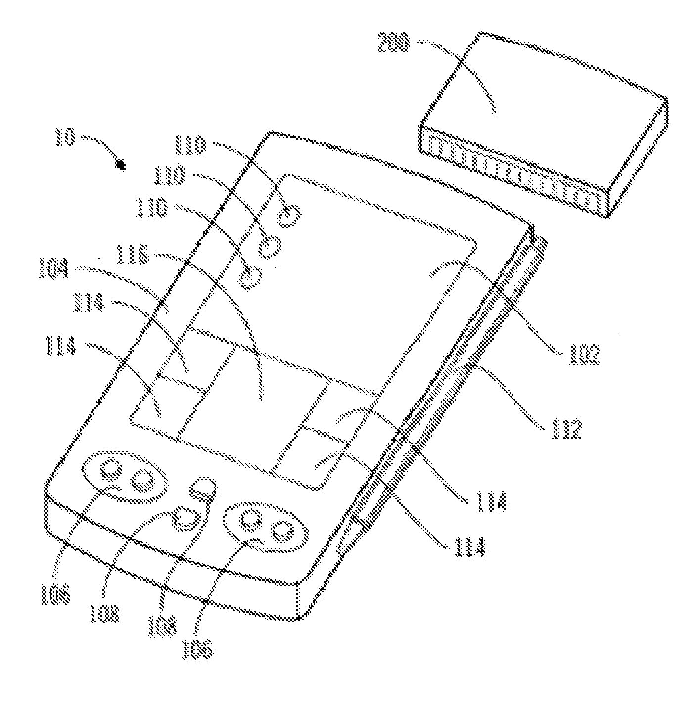
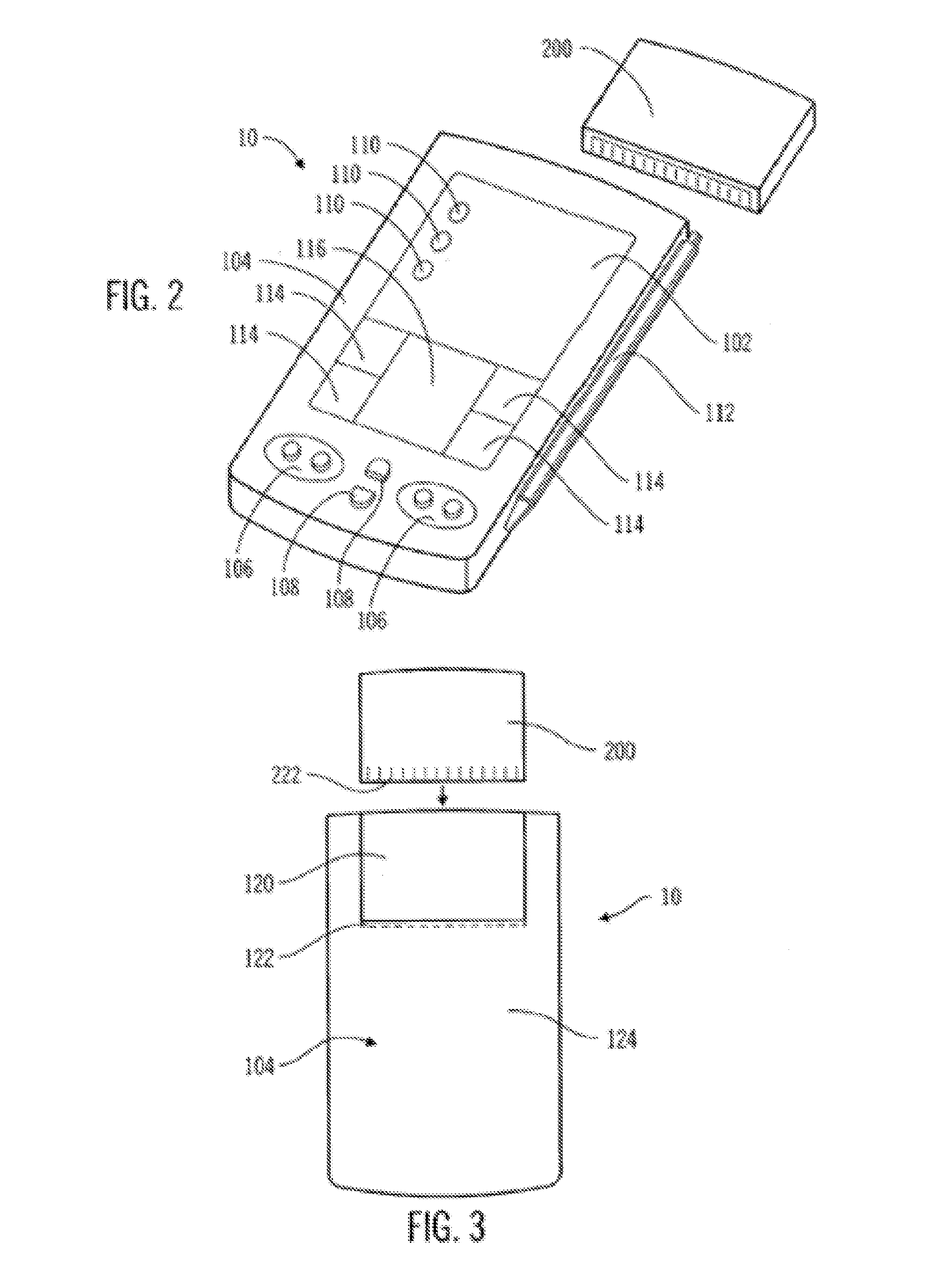
[0112]FIG. 11 is a perspective view of a medical device module 500 that interfaces with a telemetered characteristic monitor transmitter 100 in accordance with the present invention. This medical device module 500 includes a characteristic monitor 200′ as described above, and communicates with the telemetered characteristic monitor transmitter 100 to transfer data signals from a sensor set. This embodiment does not include a characteristic meter as described above. Preferably, the communication between the medical device module 500 and telemetered characteristic monitor transmitter 100 is wireless, as described above. However, in alternative embodiments, a wired connection such as shown in FIG. 18 may be used. In further alternative embodiments, the medical device module 500 may also just act as a interface and communication device for the PDA 10 to receive processed data from the telemetered characteristic monitor transmitter 100, if the telemetered characteristic monitor transmitt...

sixth embodiment

[0113]FIG. 12 is a perspective view of a medical device module 520 that interfaces with a characteristic meter 522 in accordance with the present invention. Preferably, the communication between the medical device module 520 and characteristic meter 522 is wireless, as described above. However, in alternative embodiments, a wired connection such as shown in FIG. 18 may be used. This embodiment does not include a characteristic monitor 200′ or a characteristic meter 300 within the medical device module, as described above. Rather, this embodiment provides an interface with the PDA 10 and communication capability between the PDA 10 and the characteristic meter 522.


PUM


Abstract

A medical device module for use in a system with a remote programmer and / or a personal data assistant (PDA) with at least one medical device includes a housing, at least one medical device and a processor. The housing is adapted to couple with the PDA. The at least one medical device interface is coupled to the housing for interfacing with the at least one medical device. The processor is coupled to the at least one medical device interface to process data from the at least one medical device. The processor is also capable of interfacing with the PDA.

Description

RELATED APPLICATIONS [0001] This is a continuation of U.S. patent application Ser. No. 10 / 429,385 filed May 5, 2003, which is a continuation of U.S. patent application Ser. No. 09 / 935,827 filed Aug. 23, 2001, now U.S. Pat. No. 6,641,533. U.S. patent application Ser. No. 09 / 935,827 is a continuation of U.S. patent application Ser. No. 09 / 487,423 filed Jan. 20, 2000, now U.S. Pat. No. 6,558,320, U.S. patent application Ser. No. 09 / 334,858 filed Jun. 16, 1999, now U.S. Pat. No. 6,554,798, which claims priority to U.S. Provisional Application Serial No. 60 / 096,994 filed Aug. 18, 1998, U.S. patent application Ser. No. 09 / 377,472 filed Aug. 19, 1999, which claims priority to U.S. Provisional Application Serial No. 60 / 103,812 filed Oct. 8, 1998, U.S. patent application Ser. No. 09 / 334,996 filed Jun. 17, 1999, and U.S. patent application Ser. No. 09 / 246,661 filed Feb. 5, 1999, now U.S. Pat. No. 6,248,067. All of the above patent applications and provisional applications are herein specifica...

Claims


Application Information

Patent Timeline
IPC IPC(8): A61B5/00A61M5/14A61M5/142A61M5/172G16H20/17G16H40/67
CPCA61B5/0002A61M5/1723A61B5/14532A61B5/1455A61B5/1486A61B5/7475A61B2560/0271A61B2560/0475A61B2562/0295A61M5/14232A61M5/14244A61M5/14248A61M5/16827A61M5/16854A61M5/172A61M5/365A61M2005/1403A61M2205/18A61M2205/3351A61M2205/3592A61M2205/581A61M2205/582A61N1/37235G06F19/3412G06F19/3468Y10S128/92Y10S128/903A61M2209/01A61B5/0031G16H40/40G16H20/17G16H40/67
Inventor CAUSEY, III, JAMES D.PURVIS, RICHARD E.HENKE, JAMES L.
Owner MEDTRONIC INC
Learn More