
Methods and systems for electrical power sub-metering

Active Publication Date: 2007-07-05
ABB (SCHWEIZ) AG
View PDF20 Cites 23 Cited by
  • Summary
  • Abstract
  • Description
  • Claims
  • Application Information

AI Technical Summary

Benefits of technology

[0003] In one aspect, an electrical distribution panel includes a backplane, a circuit breaker comprising a load conductor for transmitting electrical power to a load, and a load sensing assembly comprising a load sensor operatively coupled to the load conductor for detecting an electrical load of the load conductor and generating a load signal proportional to the electrical load. The load sensing assembly is selectively positionable with respect to the load conductor at a plurality of fixedly secured positions on the backplane to facilitate positioning the load sensor with respect to the load conductor.
[0004] In another aspect, a load sensing assembly includes a bracket having a slot. The bracket is configured to be coupled to an electrical distribution panel adjacent a circuit breaker having a load carrying circuit conductor. The assembly also includes a load sensor configured to be operatively coupled to the load carrying circuit conductor for generating a load signal proportional to the load carried in the load carrying circuit conductor. The load sensor is selectively positionable on the bracket at a plurality of fixedly secured positions along the slot to facilitate positioning the load sensor with respect to the load carrying circuit conductor.

Problems solved by technology

In such areas, electricity distribution to an individual customer was limited to a regulated utility entity.

Method used


Image

  • Methods and systems for electrical power sub-metering
  • Methods and systems for electrical power sub-metering
  • Methods and systems for electrical power sub-metering

Examples


Embodiment Construction

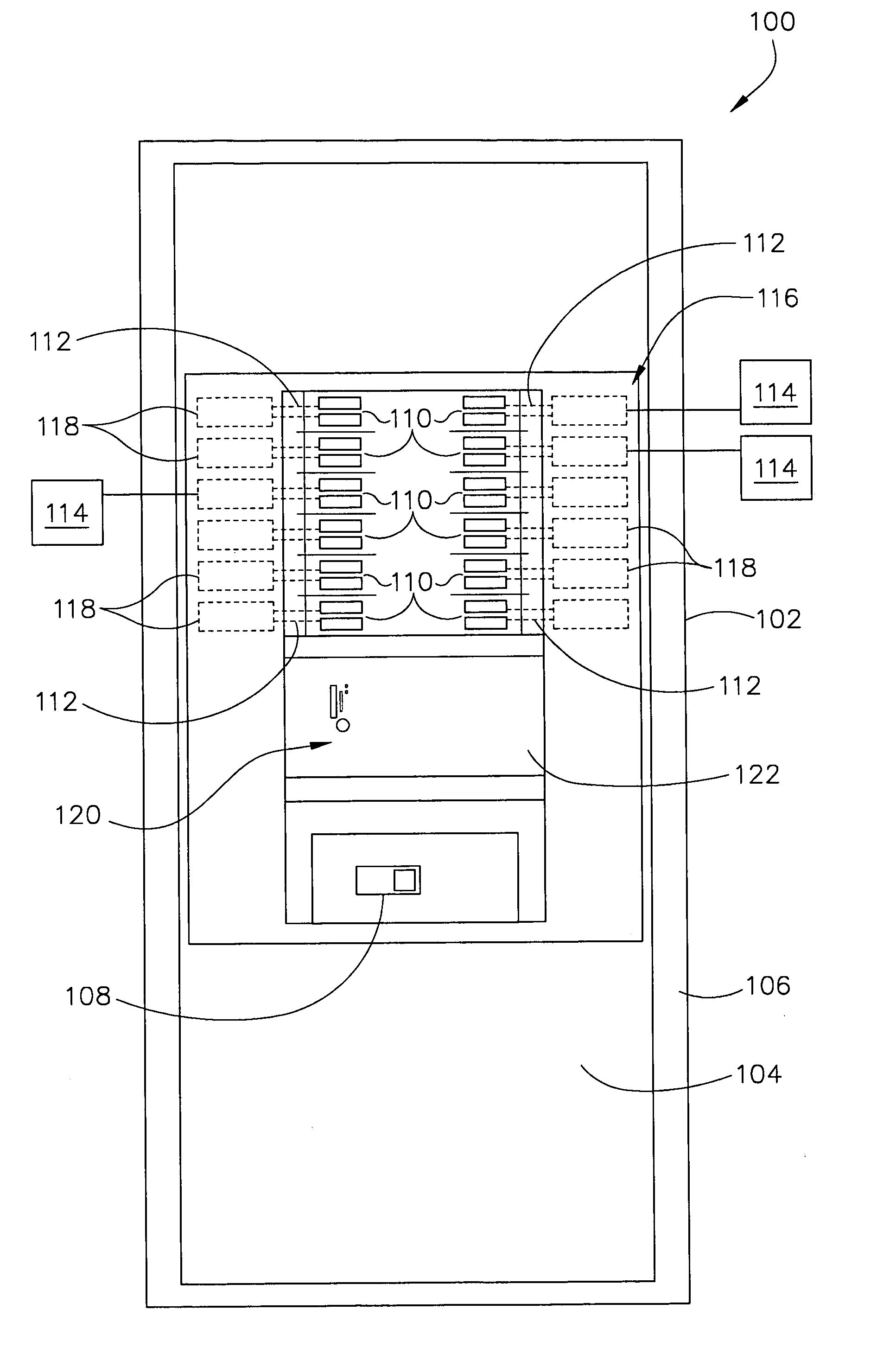
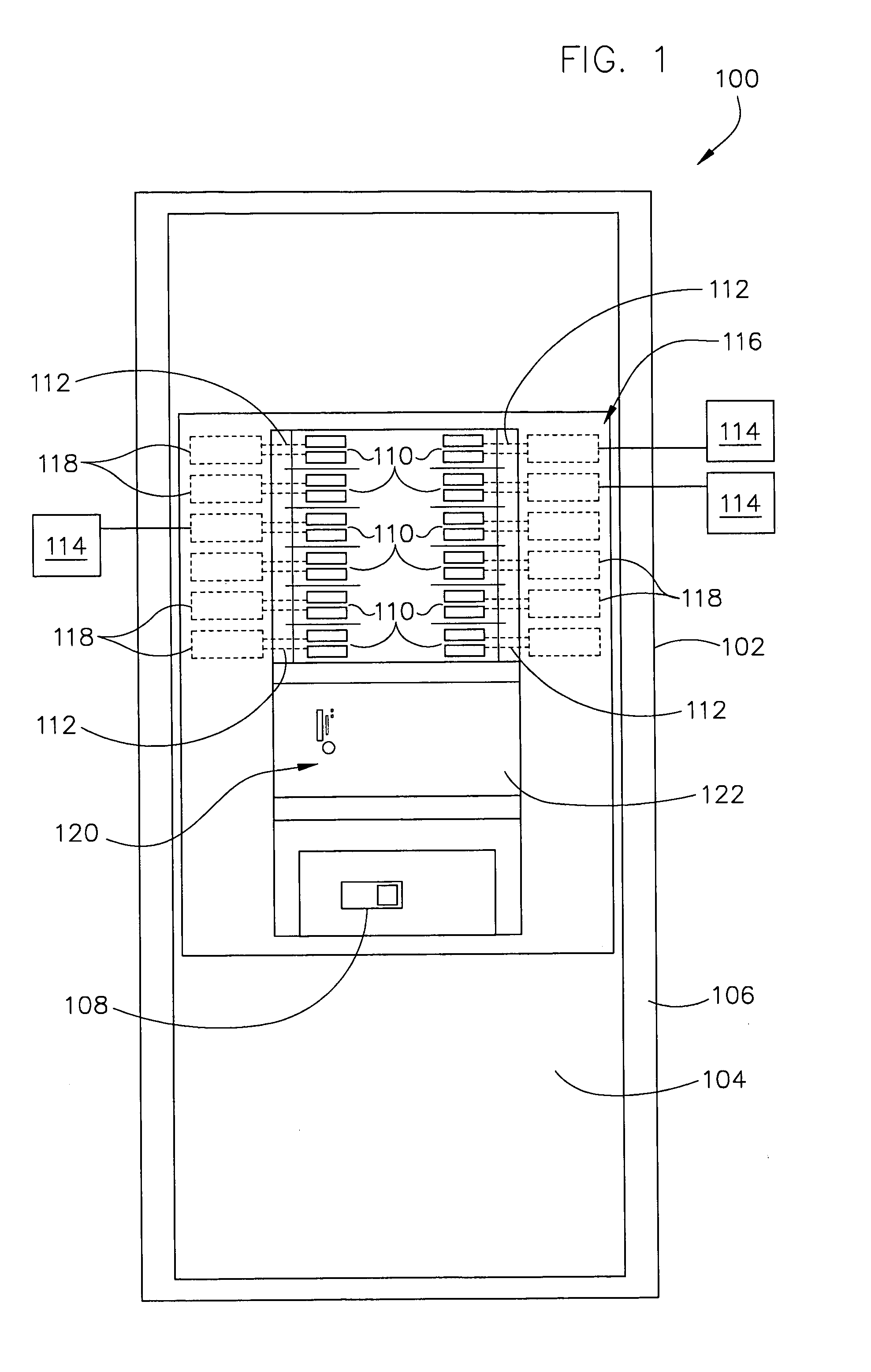
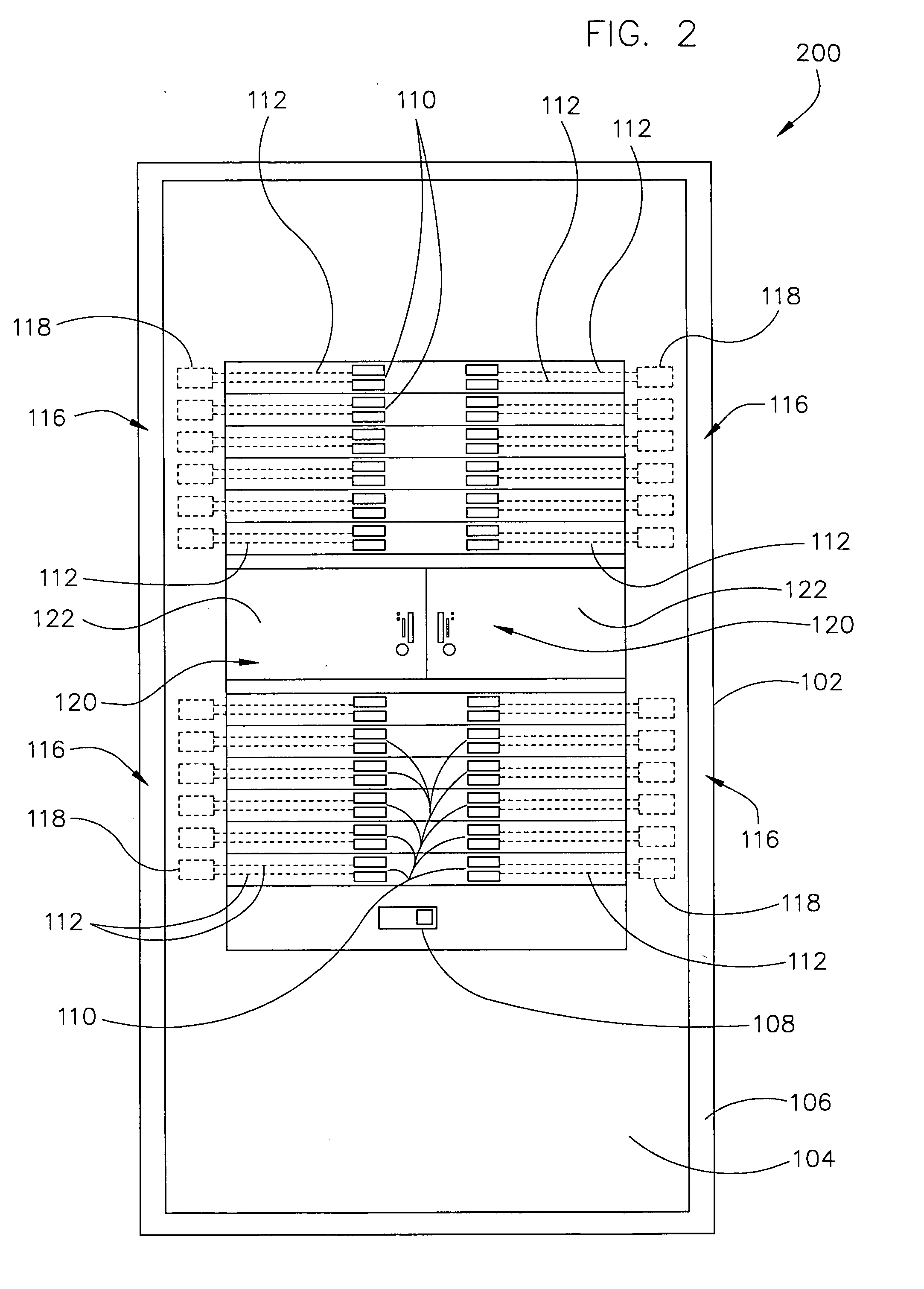
[0013]FIG. 1 is a schematic diagram of an exemplary embodiment of an electrical distribution panel 100. In the exemplary embodiment, distribution panel 100 includes a base 102 that may include one or more sidewalls (not shown) extending therefrom to define an at least partially enclosed space. A backplane 104 may be coupled to an interior surface 106 of base 102. Backplane 104 may be mounted directly on surface 106 or may be separated from surface 106 by standoffs or spacers (not shown) positioned between surface 106 and backplane 104 such that a gap (not shown) is defined between surface 106 and backplane 104. A main circuit breaker 108 may be coupled to panel 100, for example to backplane 104, such that contacts (not shown) within circuit breaker 108 engage a plurality of alternating current (AC) power lines L1, L2, neutral line N. Although panel 100 may be supplied with any suitable type of voltage, in some embodiments lines L1, L2, N supply 120 / 240 VAC, single phase, three wire ...


PUM


Abstract

An electrical distribution panel includes a backplane, a circuit breaker comprising a load conductor for transmitting electrical power to a load, and a load sensing assembly comprising a load sensor operatively coupled to the load conductor for detecting an electrical load of the load conductor and generating a load signal proportional to the electrical load. The load sensing assembly is selectively positionable with respect to the load conductor at a plurality of fixedly secured positions on the backplane to facilitate positioning the load sensor with respect to the load conductor.

Description

BACKGROUND OF THE INVENTION [0001] This invention relates generally to electrical distribution panels, and more specifically to methods and systems for sub-metering electrical power supplied from electrical distribution panels. [0002] At least some government entities, such as states, are permitting, and in some cases requiring, deregulation of wholesale electricity distribution. In such areas, electricity distribution to an individual customer was limited to a regulated utility entity. With new regulations in effect, a landlord, for example an apartment building owner, may now purchase bulk power for the apartment building and resell the power to the individual apartment residents. Heretofore, the metering of power distributed to individual apartments was performed by individual demand meters corresponding to each apartment and owned by the regulated utility. A new metering scheme, to take advantage of the deregulated environment, may allow for only one utility electrical demand me...

Claims


Application Information

Patent Timeline
IPC IPC(8): H02H3/00
CPCG01R22/06H02B1/04G01R22/065
Inventor CAGGIANO, ROBERT J.REDDITHA, SURESHPARBHU, RAGHUNATH
Owner ABB (SCHWEIZ) AG
Learn More