
Fuel cell electric power generating system

Active Publication Date: 2007-06-28
BALLARD POWER SYSTEMS
View PDF0 Cites 36 Cited by
  • Summary
  • Abstract
  • Description
  • Claims
  • Application Information

AI Technical Summary

Benefits of technology

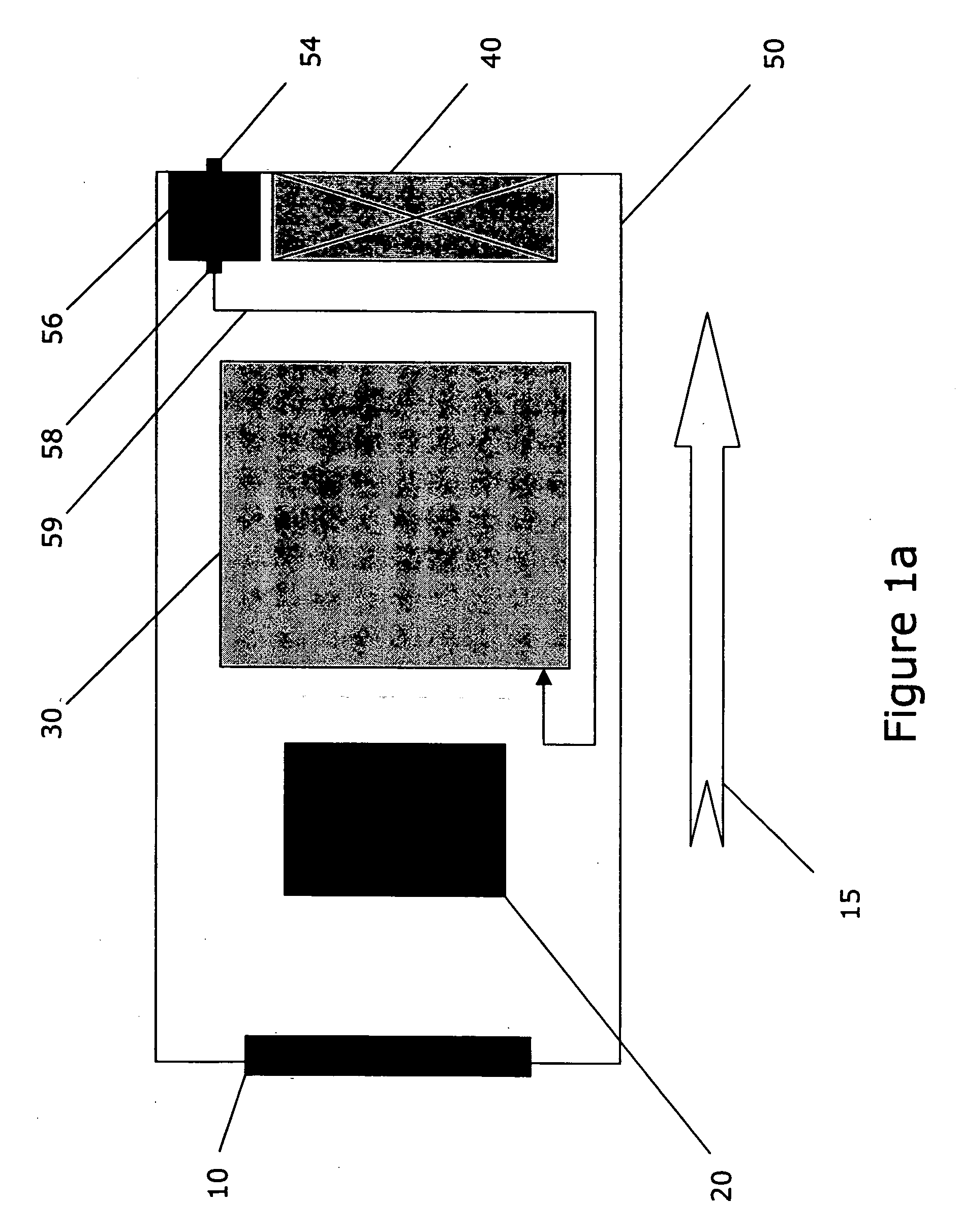
[0006] A fuel cell electric power generation system using air as both a coolant and an oxidant comprises an electric power generation subsystem, an air filter subsystem, a power electronics unit (PEU) subsystem comprising a DC / DC converter, and an air fan subsystem. The subsystems are arranged such that air circulation through the system is improved and the risk of moisture damage to sensitive PEU components is reduced. In one embodiment, the air filter subsystem is positioned ahead of the PEU subsystem, which is positioned ahead of the power generation subsystem, which is positioned ahead of the air fan subsystem in the direction of air flow, such that air is drawn by the air fan subsystem through the air filter subsystem, over the PEU subsystem, and through the electric power generation subsystem, providing filtered air to cool the PEU prior to entering the fuel cell stack to provide oxygen for the electrochemical reaction.

Problems solved by technology

However, air that is moved away from the reaction sites of these systems can still pick up some of the water involved in the chemical process and experience an increase in moisture content as it cools the system.
The architectural layouts of fuel cell systems of the prior art have consisted of moving air throughout the system in a manner that increases the risk that moist air will cause damage to the sensitive components such as the power and control electronics unit (PEU) or that air heated by the fuel cell stack will not sufficiently cool the PEU and thus increase the risk of premature failure of the PEU.

Method used


Image

  • Fuel cell electric power generating system
  • Fuel cell electric power generating system
  • Fuel cell electric power generating system

Examples


Embodiment Construction

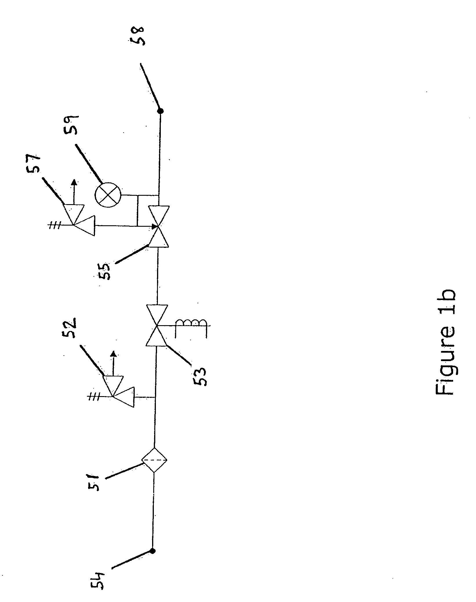
[0013] As illustrated in FIG. 1a, an ambient air and oxidant cooling system consists of an air filter (10), a power electronics unit (PEU) (20), a fuel cell stack (30), a fuel supply system (56), and a fan (40). Although only a single air filter or fan is depicted, configurations with more than one air filter or fan can also be envisioned. Also, the fan can be provided with a tachometer that can serve as both a fan speed measurement device or as a system on / off indicator.

[0014] The PEU of the ambient air and oxidant cooling system depicted in FIG. 1 a comprises a power supply with a DC / DC converter that can have an architecture and a power conversion methodology as shown in patent application US20040217732. The power supply comprises a main power converter architecture that allows the fuel cell stack to operate independently of a desired output voltage. The fuel cell stack may be directly connected to the main power converter eliminating high current switches and diodes. Switches a...


PUM


Abstract

A fuel cell electric power generation system using air as both a coolant and an oxidant comprises an electric power generation subsystem, an air filter subsystem, a power and control electronics unit (PEU) subsystem comprising a DC / DC converter, and an air fan subsystem. The subsystems are arranged such that air circulation through the system is improved and the risk of moisture damage to sensitive PEU components is reduced. In one embodiment, the air filter subsystem is positioned ahead of the PEU subsystem, which is positioned ahead of the power generation subsystem, which is positioned ahead of the air fan subsystem in the direction of air flow, such that air is drawn by the air fan subsystem through the air filter subsystem, over the PEU subsystem, and through the electric power generation subsystem, providing filtered air to cool the PEU prior to entering the fuel cell stack to provide oxygen for the electrochemical reaction.

Description

BACKGROUND OF THE INVENTION [0001] 1. Field of the Invention [0002] The invention relates to a fuel cell electric power generating system. More specifically, to a fuel cell system using air cooling. [0003] 2. Description of the Related Art [0004] Fuel cells are electrochemical devices that generate power from a chemical reaction. Hydrogen and oxygen are typically the primary fuel and oxidant, respectively, involved in the reaction. The reaction takes place at a membrane electrode assembly (MEA). The MEA has an anode and a cathode electrode and a membrane electrolyte for letting protons pass through. An additional product of the reaction is heat. Fuel cells have a load-dependent electrical efficiency of about 50%. The heat losses must be carried off by a corresponding cooling system. In most cases this is accomplished by means of water circulation with an external cooler. Air-cooled cells or stacks are also known. Air-cooled systems, where the air serves both as a coolant and as an o...

Claims


Application Information

Patent Timeline
IPC IPC(8): H01M8/04H01M8/10H01M2/08
CPCH01M8/0256H01M8/0276H01M8/04014H01M8/04089H01M8/04858H01M8/0687H01M8/242Y02E60/50H01M8/0263H01M8/0267H01M8/0273H01M8/0297H01M8/241H01M8/2483
Inventor COLBOW, KEVIN M.COERTZE, RUDOLF J.HENDERSON, ANDREW J.CHIEM, BIEN H.ARTIBISE, ROBERT H.JUNG, SEUNGSOO
Owner BALLARD POWER SYSTEMS
Learn More