Al technical title is built by PatSnap Al team. It summarizes the technical point description of the patent document.
a technology for empennage and aircraft, applied in the field of rotating fittings, can solve the problems of insufficient transmission, appearance of certain bending loads which the structure has to withstand, and extra weight for the structure of the fuselag
Inactive Publication Date: 2007-06-28
AIRBUS OPERATIONS SL +1
View PDF5 Cites 2 Cited by
Summary
Abstract
Description
Claims
Application Information
AI Technical Summary
This helps you quickly interpret patents by identifying the three key elements:
Problems solved by technology
Method used
Benefits of technology
[0016]The set of the three fittings passes the vertical load of the empennage to the fuselage frame due to a double shear of the receiving pins of the fittings to the frame. Moreover, as there are two lugs on both sides of the empennage fitting, the system is secure against possible failures, which means that in the event of a failure of one of the lugs, the other supports the load without endangering the integrity of the aircraft. Likewise, the central fitting helps to provide stability for the frame.
[0017]It is evident that the rotation fitting with the characteristics described above and its assembly contribute towards the stiffness of the fuselage towards torsion, given that it permits the configuration of a closed frame.
Problems solved by technology
This system is adequate up to a certain load level, though it is insufficient for transmitting high loads from the empennage to the fuselage.
In this latter case, the fuselage fitting presents an eccentricity with regard to the plane of the frame of the fuselage, which gives rise to the appearance of certain bending loads which the structure has to withstand.
Therefore, a series of counter-fittings needs to be provided which implies a extra weight for the structure of the fuselage, in addition to implying a high cost and requiring greater maintenance.
Method used
Image
Click on the blue label to locate the original text in one second.
Reading with bidirectional positioning of images and text.
Examples
Embodiment Construction
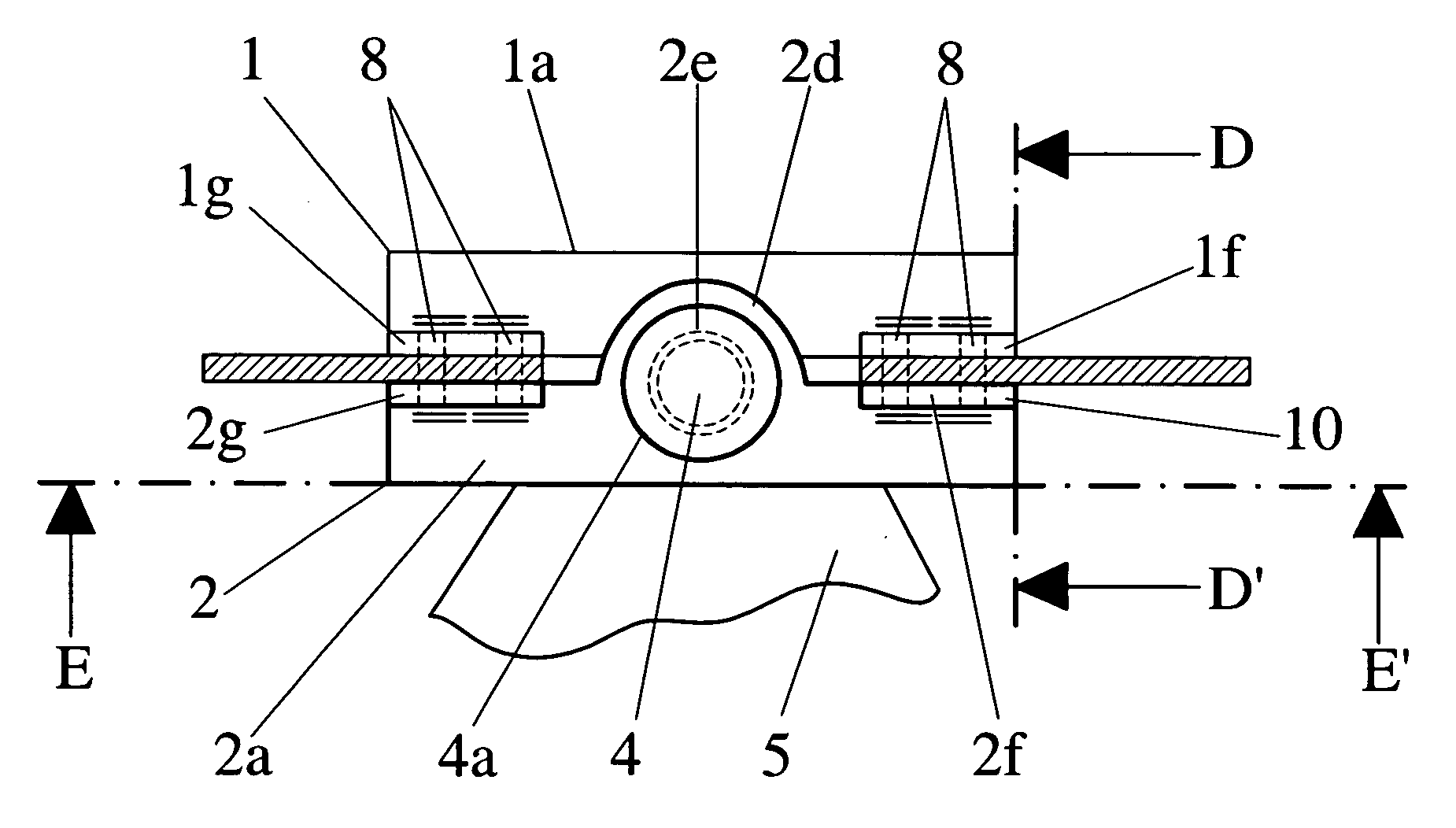
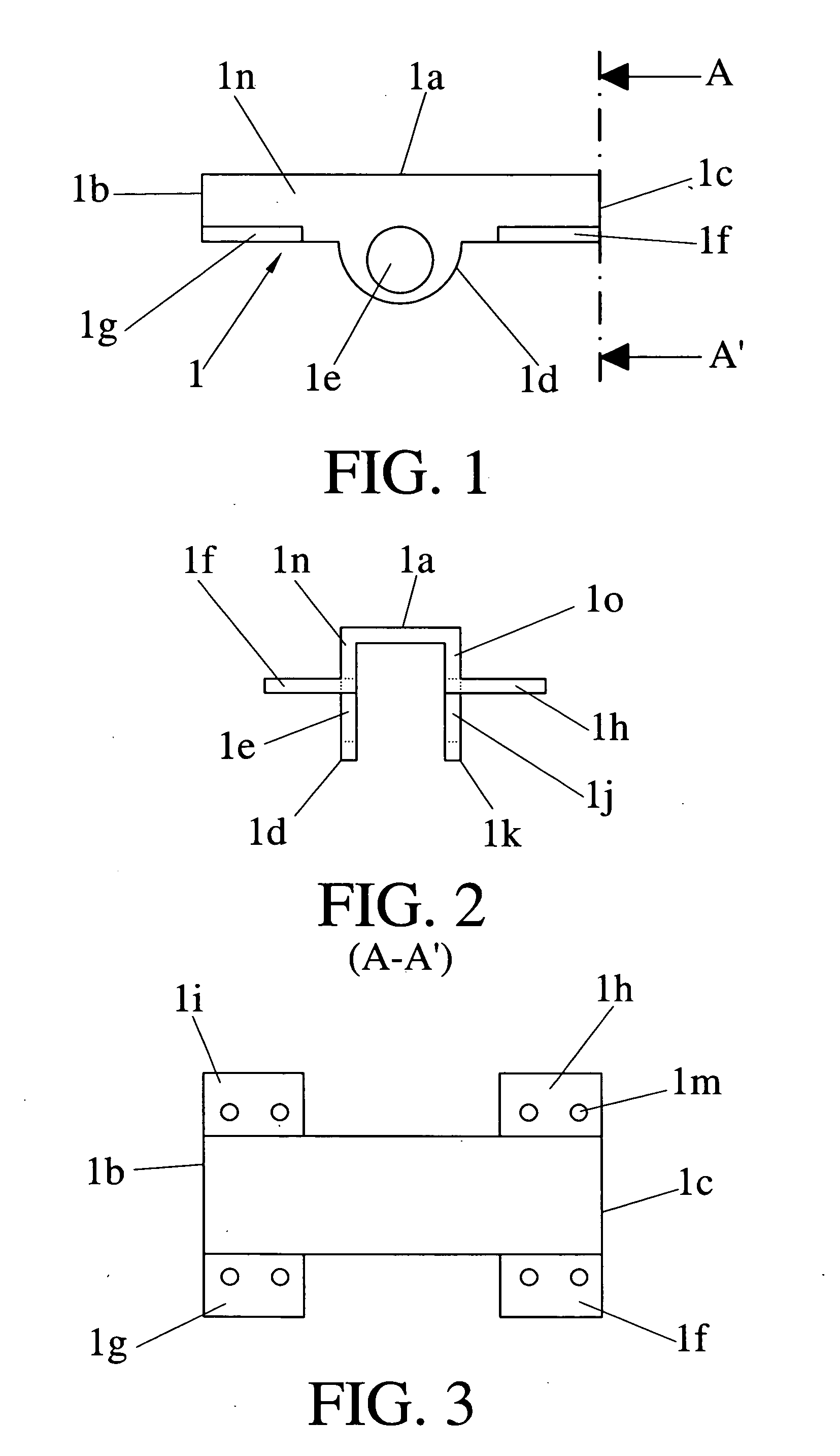
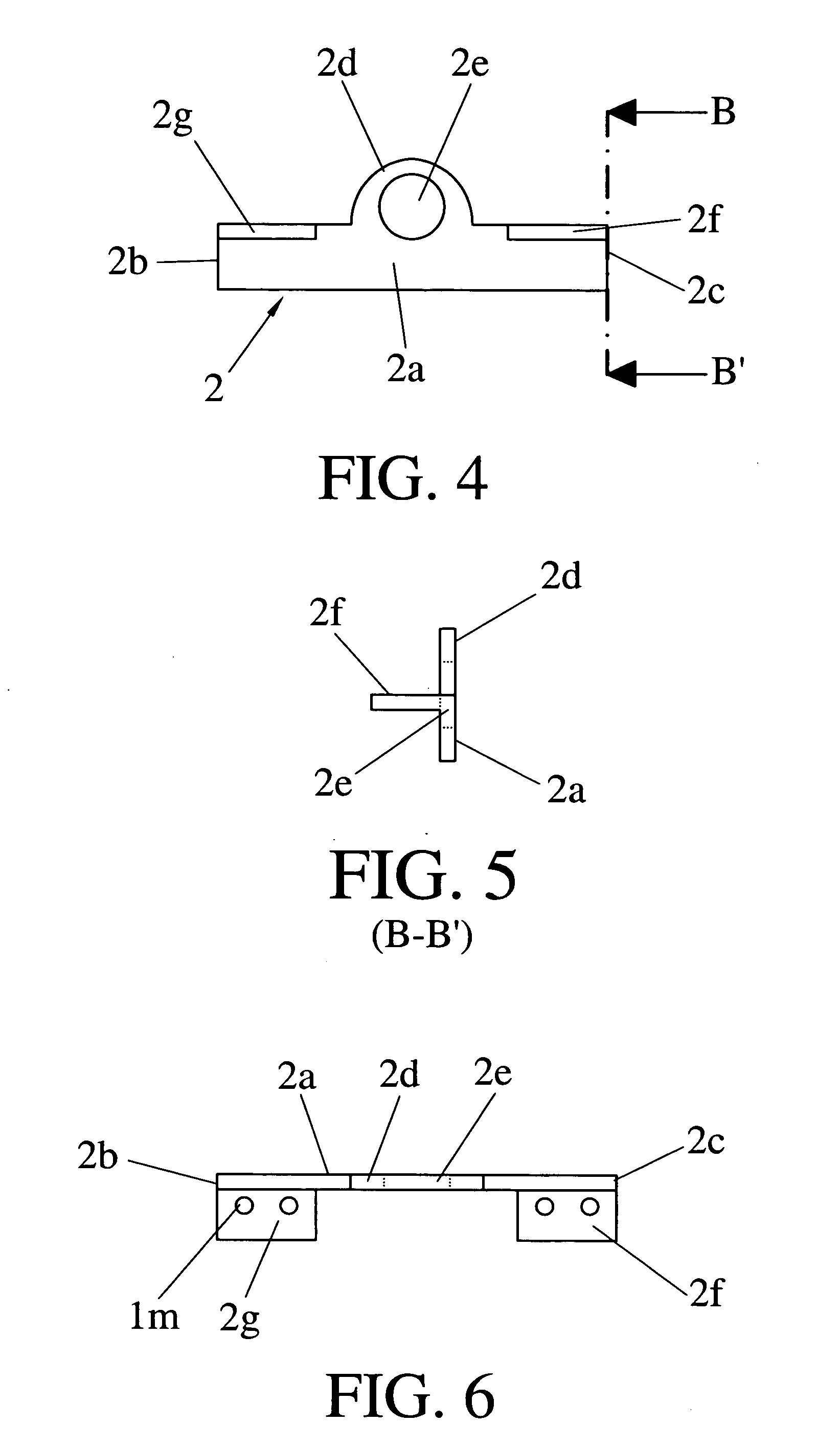
[0008]The present invention has the aim of overcoming the drawbacks of the receiving fittings existing in the prior art by means of a rotation fitting secured to a fixed element for the linkage of a moving element, particularly and preferably secured to a frame of the fuselage of an aircraft for the linkage of a receiving element of the empennage of the aircraft, said rotation fitting being designed in such a way that, being secured to a closed frame of the fuselage, the axis of rotation of the receiving element of the empennage is located within the plane of that frame with the aim of eliminating the eccentricity of the load with respect to the plane of the frame and therefore eliminating the appearance of the associated bending loads. Owing to the safety requirements demanded of structural elements that are responsible for the safe operation of the aircraft, the rotation fitting includes a central fitting, a first side fitting and a second side fitting with the characteristics tha...
PUM
Abstract
Rotation fitting secured to a frame (6) of the fuselage of an aircraft and linked to a receiving element secured to the empennage (5) which comprises a central fitting (1) and two side fittings (2,3), the central fitting (1) presenting two lugs (1d,1k) with an opening (1e,1j) each and four side wings (1g,1f,1i,1h), and each one of the side fittings (2,3) presenting a lug (2d,3d) with an opening (2e,3e) each and two side wings (2g,2f,3g,3f), the central fitting (1) being secured to a surface of the frame (6) and the side fittings (2,3) in an opposite surface of the frame (6), such that the frame (6) is arranged between the central fitting (1) and the two side fittings (2,3), such that the lugs (1d,1k) of the central fitting (1) make contact with the lugs (2d,3d) of the side fittings, with all the openings (1e,1j,2e,3e) being aligned in order to house a pin (4) associated with the receiving element secured to the empennage (5).
Description
TECHNICAL FIELD OF THE INVENTION[0001]This invention belongs to the technical field of rotation fittings secured to a fixed element which link a moving element, and more particularly to rotation fittings used in the aeronautical sector, specifically rotation fittings secured to a frame of the fuselage of an aircraft which link a receiving element secured to the empennage of the aircraft.PRIOR ART OF THE INVENTION[0002]Conventionally, in the prior art, for the case of a horizontal empennage, with adjustable angle of incidence, the reception of the empennage to the fixed structure of the fuselage is done at three points, two rear ones, which define the axis of rotation around which the empennage pivots, and a forward one to which the actuator is hooked with which the rotary movement, and therefore the angle of incidence of the empennage, is regulated.[0003]The linkage at the two rotary points stated above is effected by means of separate rotation fittings joined integrally by means of...
Claims
Application Information
Patent Timeline
Application Date:The date an application was filed.
Publication Date:The date a patent or application was officially published.
First Publication Date:The earliest publication date of a patent with the same application number.
Issue Date:Publication date of the patent grant document.
PCT Entry Date:The Entry date of PCT National Phase.
Estimated Expiry Date:The statutory expiry date of a patent right according to the Patent Law, and it is the longest term of protection that the patent right can achieve without the termination of the patent right due to other reasons(Term extension factor has been taken into account ).
Invalid Date:Actual expiry date is based on effective date or publication date of legal transaction data of invalid patent.
Patent Type & Authority Applications(United States)