
Display device

a technology of display device and display screen, which is applied in the direction of identification means, television systems, instruments, etc., can solve the problems of poor operability, uneven adjustment operation, and poor appearance, and achieve excellent operability and appearance of the stand structur

Inactive Publication Date: 2007-06-28
SONY CORP
View PDF4 Cites 56 Cited by
  • Summary
  • Abstract
  • Description
  • Claims
  • Application Information

AI Technical Summary

Benefits of technology

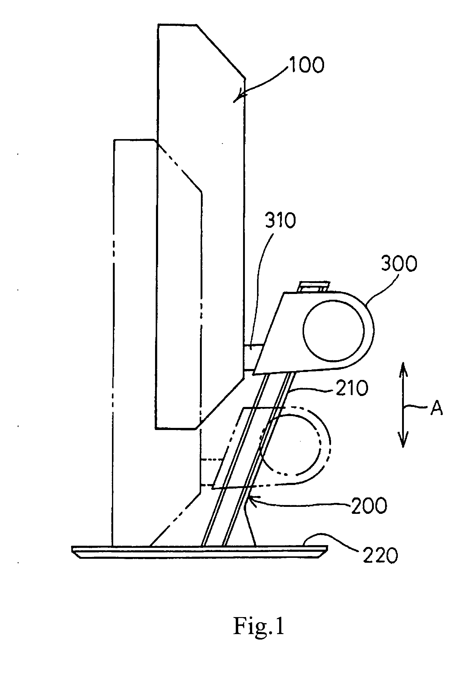
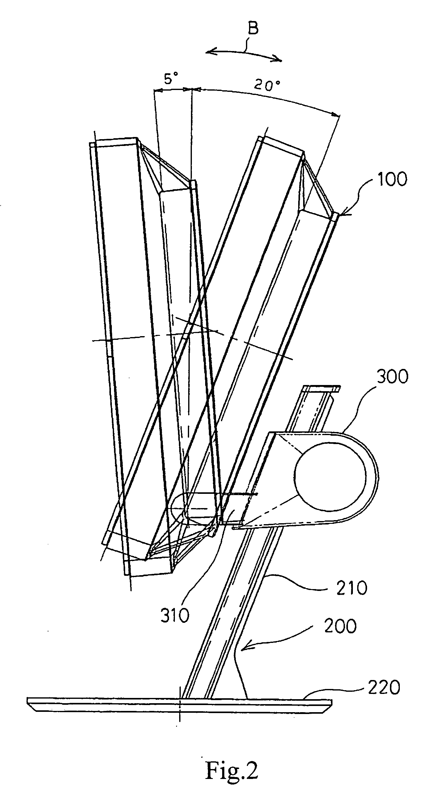
[0009] The display apparatus of the present invention has a structure in which a slide bracket is assembled to a post having a linear guide section to mesh a rack member provided on the post side with a gear provided on the slide bracket side, and also a spiral spring is provided between the gear and the slide bracket, wherein the spiral spring imparts a biasing force to the gear such that the gear rotates in such a direction as to cause the slide bracket to move up, and a cover body for accommodating this spiral spring therein is provided. As a result of the structure, height adjustments and tilting angle adjustments of the display panel section can be made smoothly, and hence a stand structure excellent in operability as well as appearance can be provided.

Problems solved by technology

For example, in the related art disclosed in the above-mentioned Patent Document 1, it is required to adjust the height of the display panel section by operating an operation knob, which addresses a shortcoming that the operability is not satisfactory.
Further, in the related art disclosed in the above-mentioned Patent Document 2, even if position adjustments can be made by directly operating the display panel section, due to its configuration in which the slide section slides along the curved surface, adjustment operation is not smooth, and additionally, the structures of the Conston spring and the like are seen from the outside, which addresses a shortcoming that the appearance is not satisfactory.

Method used


Image

  • Display device
  • Display device
  • Display device

Examples


Embodiment Construction

[0017] An exemplary embodiment of a display apparatus according to the present invention will be described below.

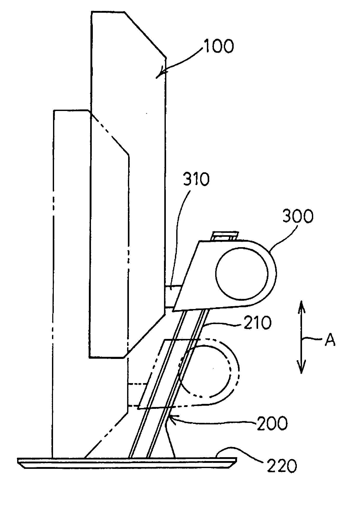
[0018]FIGS. 1, 2 are side views showing the appearance of a display apparatus according to an exemplary embodiment of the present invention. FIG. 1 shows moving up and down operation; and FIG. 2 shows tilting movement.

[0019] Further, FIGS. 3, 4, 5 are perspective views showing internal structures of the display apparatus according to the present exemplary embodiment. FIG. 3 shows a state in which a post and a slide bracket are coupled together; FIG. 4 shows a state in which the slide bracket is disassembled; and FIG. 5 shows a state in which the interior of the slide bracket is further disassembled.

[0020] Furthermore, FIGS. 6, 7 are diagrams showing a state in which the post and the slide bracket of the display apparatus according to the present exemplary embodiment are assembled. FIG. 6 is a schematic plan view; and FIG. 7 is a horizontal cross-sectional view of a mai...


PUM


Abstract

A display apparatus in which a supporting structure excellent in operability and appearance is realized is provided. A slide bracket (300) is provided to move up and down freely on a post (210) of a stand section (200), and a display panel section (100) and the slide bracket (300) are coupled together with a hinge section (310). The post (210) is provided with rack members (230A, 230B), which are meshed with gears (340A, 340B) provided on the slide bracket (300). Frictional rings (390) are provided to impart a frictional force to the rotating operation of the gears (340A, 340B) so that the slide bracket (300) stays at an arbitrary height of the post (210). Between the gears (340A, 340B) and the slide bracket (300), a spiral spring (370) is incorporated, and the spiral spring (370) is accommodated within a drum (360). The spiral spring (370) acts as a biasing force for causing the slide bracket (300) to move up through its biasing the gears (340A, 340B) to rotate.

Description

TECHNICAL FIELD [0001] The present invention relates to a display apparatus having a flat display panel section and a stand section, used for peripheral equipment of, e.g., a personal computer. BACKGROUND ART [0002] Conventionally, a display apparatus of this type has required a structure for supporting a display panel section so as to be adjustable to an arbitrary height and tilting angle. And various forms of stand sections therefor have been proposed. [0003] For example, a structure has been proposed, in which a display panel section is mounted onto a guide section formed on a post of a stand section so as to be able to move up and down, and also a rack and a gear for adjusting the position of this display panel section are provided to adjust the height of the display panel section through the rotating operation of the gear (see, e.g., Patent Document 1 (Japanese Patent Application Publication No. 2001-42779 (FIG. 4)). [0004] Further, another structure has been proposed, in which...

Claims


Application Information

Patent Timeline
IPC IPC(8): F16M11/00F16M11/04H04N5/64F16M11/10F16M11/18F16M11/24G09F9/00
CPCF16M11/10F16M11/18F16M2200/048F16M11/24F16M11/2092
Inventor TAKADA, TSUYOSHIHARATA, TOMOHIRO
Owner SONY CORP
Learn More